


page 7
Grinding
A Type 27 guard must be installed when using a grinding
wheel to provide maximum protection for the operator if the
wheel should break.
WARNING!
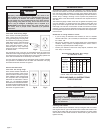
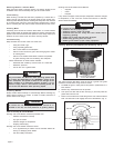
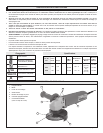
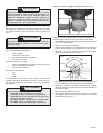
Flange nut position for 1/8" or less thick wheels
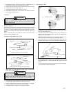
Flange nut position for 1/4" thick wheels
Fig. 5
Flange nut
Boss
Spindle
Grinding wheel
Flange
Fig. 6
Boss
Flange nut
Spindle
Grinding wheel
Flange
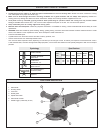
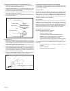
Selecting Wheels
Grinding is the cutting action of thousands of abrasive grains on the face
of a grinding wheel. When grinding metals such as steel and iron, choose
an aluminum oxide grinding wheel. Select a silicon carbide grinding wheel
for stone and concrete. Use cotton reinforced wheels for non-ferrous
metals.
Type 27 reinforced 1/8" cut-off wheels are suited for small cut-off and
shallow notching operations only.
Installing Grinding Wheels (Fig. 5 & 6)
1. When guard is properly positioned, place flange on spindle with
flange facing away from tool.
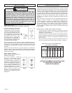
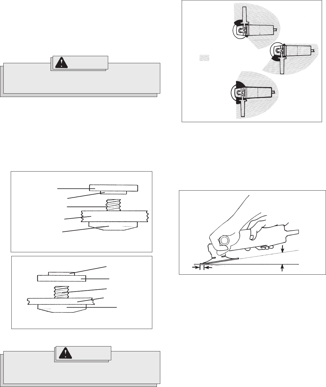
1. Depending on your job, position the guard to provide maximum pro-
tection for the operator (Fig. 7).
2. If you have just installed a grinding wheel or are just beginning a
period of work, test wheel by letting it spin for one minute before
applying it to the workpiece.
NOTE: Out-of-balance wheels can mar workpiece, damage the tool,
and cause stress to wheel that may cause wheel failure.
3. Firmly grasp body of tool and side handle before starting and while
using tool. Allow wheel to come to full speed before starting to grind.
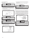
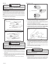
4. When grinding, hold sander/grinder at a 5
o
to 15
o
angle as shown, using
constant pressure for a uniform finish. Too great an angle causes
concentrated pressure on small areas which may gouge or burn work
surface.
5. Control pressure and surface contact between disc and workpiece.
Too much pressure slows cutting speed.
2. Place selected wheel on spindle and align with flange. Position flange
nut according to wheel thickness as shown (Fig. 5 & 6).
3. Press the spindle lock button while turning flange nut clockwise.
Tighten securely with the spanner wrench provided.
4. To remove wheel, unplug tool and reverse procedure.
To reduce the risk of injury, do not use the spindle lock
button to stop the spindle while the tool is in use or is
coasting after shut-off. This will result in tool damage.
WARNING!
5. To remove the guard, unplug tool and place it upside down on a
level surface. Remove any accessories from spindle.
6. Press in the lock lever and rotate the guard to line up the four tabs
with the four slots as shown in (Fig. 4).
7. Lift the guard straight up and away from the tool.
8.To adjust the guard, press in the lock lever and rotate the guard to
one of the five detents (Fig. 3).
Fig. 7
Operator's Zones
Fig. 8
Hold at a 5° to 15° angle
Grinding (Fig. 7 & 8)