


page 7
TOOL ASSEMBLY
Mounting the Miter Saw
To prevent the tool from sliding, falling or tipping during operation, the
saw can be mounted to a supporting surface such as a level, sturdy
work table or bench. Position the saw and workbench to allow adequate
room for cross-cutting long workpieces. To mount the saw, insert fas-
teners through the four holes in the base of the saw.
Installing the Clamp Handle
The clamp handle locks the selected miter angle. The tool is shipped with
the handle unassembled. To install the handle, thread it clockwise into
the tool. To tighten the handle and lock the angle, turn the handle clock-
wise. To loosen and unlock, turn it counterclockwise.
Installing Dust Bag or Vacuum Hose
A dust bag is provided to collect sawdust. To install the dust bag, push
the dust bag onto the dust ejection port. This port is also designed to
accept a standard workshop vacuum hose. To collect sawdust directly
into a vacuum cleaner, attach the vacuum cleaner hose to the dust
ejection port and turn it on before cutting.
Raising and Lowering the Saw Head
The saw head locks down for transporting and storing the tool. The tool
is shipped with the saw head locked down. To unlock it, press and hold
down the saw head and simultaneously pull out the lock pin. To lock the
saw head, press and hold down the saw head and then push in the lock
pin.
Lock-Off
There is a hole in the trigger through which a padlock will fit to lock the
tool when it is not in use. Use a padlock with a 1/4" shackle and always
unplug the tool before installing it (padlock not supplied with tool).
WARNING!
To reduce the risk of injury, always unplug tool before
attaching or removing accessories or making adjustments.
Use only specifically recommended accessories. Others
may be hazardous.
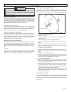
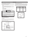
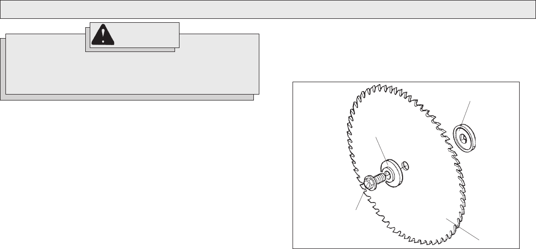
Installing and Changing Blades (Fig. 1)
MILWAUKEE offers a full line of carbide-tipped Miter Saw blades. Al-
ways use clean, sharp blades because dull blades tend to overload the
tool, bind and cause pinching. Use only 10" blades rated at least 5500 RPM.
Fig. 1
Outer flange
Inner flange
Blade
Blade screw
1. To install a blade, unplug the tool.
2. Raise the saw head.
3. Loosen (do not remove) the two screws on the blade screw guard
counterclockwise.
4. Rotate blade screw guard to expose blade screw.
5. Press in the spindle lock and rotate the spindle until the lock en-
gages.
6. Use the wrench supplied with the tool to loosen and remove the left-
hand thread blade screw clockwise (wrench is stored behind the
right fence in wrench holder).
7. Lift and hold up the lower guard.
8. Remove the outer blade flange, blade (if present), and the inner
blade flange. Wipe the flanges and spindle to remove dust and
debris.
9. Install the inner blade flange as shown.
10. Match the arrow on the blade with the arrow on the tool casting.
Install the selected blade by sliding the blade between the gap in the
fence and then lifting the blade up to the spindle.
11. Install the outer blade flange.
12. Press in the spindle lock and rotate the blade until lock engages
while replacing and securely tightening the blade screw counter-
clockwise with supplied wrench.
13. Rotate the blade screw guard into position and securely tighten the
two screws clockwise. Return the wrench to the wrench holder.
14. Lower the saw head and check the clearance between the blade
and the turntable. The blade should rotate freely.
NOTE: If you are installing the blade for the first time, be aware that
kerf plates (which come uncut) need to be cut before use. See
"Cutting the Kerf Plate Slot".
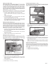
A Note About Kerf Plates
The purpose of the kerf plate is to eliminate tear-out (splintering along the
cut) by providing edge support for the workpiece. Because saw blades
can vary in width, to get the best possible edge support and alignment
and to reduce tear-out, each blade (or width of blade) should have its
own kerf plate.