


page 6
TOOL ASSEMBLY
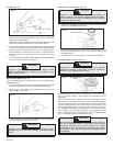
Installing Side Handle
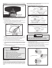
The side handle may be installed on the top of the gear case or on either
side of gear case for right or left handed use. Position side handle in the
location which offers best control and guard protection. To install, thread
side handle into side handle socket on desired side of gear case and
tighten securely.
Wear safety goggles or glasses with side shields. Always
unplug tool before attaching or removing accessories. Only
use accessories specifically recommended for these tools.
Others may be hazardous. Protect others in work area from
debris such as chips and sparks. Provide barriers or shields
as needed.
WARNING!
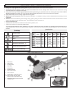
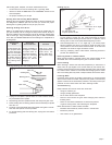
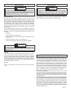
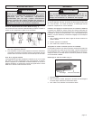
Removing and Replacing Quik-Lok
®
Cords (Fig. 1)
MILWAUKEE's exclusive Quik-Lok
®
Cords provide instant field replace-
ment or substitution.
1. To remove the Quik-Lok
®
Cord, turn the cord nut 1/4 turn to the left
and pull it out.
2. To replace the Quik-Lok
®
Cord, align the connector keyways and
push the connector in as far as it will go. Turn the cord nut 1/4 turn
to the right to lock.
OPERATION
Fig. 1
To reduce the risk of injury, wear safety goggles or glasses
with side shields. Unplug the tool before changing accesso-
ries or making adjustments.
WARNING!
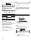
Controlled Start (Cat. No. 6154-20, 6156-20, and 6160-20)
When used on 120 Volts AC, the controlled start feature reduces the
torque reaction "jerk" when its trigger is pulled. The controlled start
feature works only with AC.
Speed Control Dial (Cat. No. 6154-20 and 6156-20)
The speed control dial controls the sander/grinder's maximum rotations
per minute. Dial settings range from numbers 1 through 5. Lower num-
bers correspond to lower speeds and higher numbers correspond to
higher speeds. Use the setting that best suits your job.
1. To control the speed, set the dial to the desired number.
2. Pull the trigger.
3. To stop the tool, release the trigger.
Constant Speed Tachometer (Cat. No. 6160-20)
The constant speed tachometer, which keeps the tool's revolutions per
minute (9000 RPM) at an almost constant speed even under load. The
tachometer also helps prevent tool overheating. The tool switches itself
off automatically when the motor is overloaded. It can be restarted by
squeezing the paddle trigger again.
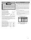
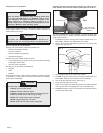
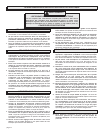
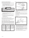
Lock-off button
Lock-on button
Fig. 2
Use sanding discs and grinding wheels that are:
correct size as written on tool's nameplate.
correct wheel type and grit for the job.
rated at or above the RPM listed in the "WARNING" section on the
tool's nameplate.
1. Plug in the tool.
2. To start the tool, flip the lock-off button and simultaneously squeeze
the paddle trigger.
3. Release paddle trigger to stop tool.
Lock-On Button (Fig. 2) (Cat. No. 6148, 6149-20, 6154-20 & 6156-20)
The lock-on button holds the trigger in the ON position for continuous full
speed use.
1. To lock the paddle trigger, hold in the lock-on button after pulling the
paddle trigger. Then release the paddle trigger.
2. To unlock the paddle trigger. Pull the paddle trigger and release. The
lock-on button will pop out.
Sanding Disc and Grinding Wheel Selection
To reduce the risk of personal injury and damage to the tool,
use ONLY accessories rated at or above the RPM listed on the
"WARNING" section of the tool's nameplate.
WARNING!
Starting and Stopping the Motor (Fig. 2)