


page 9
Selecting Wheels
Grinding is the cutting action of thousands of abrasive grains on the face
of a grinding wheel. When grinding metals such as steel and iron, choose
an aluminum oxide grinding wheel. Select a silicon carbide grinding wheel
for stone and concrete. Use cotton reinforced wheels for non-ferrous
metals.
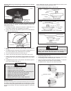
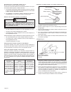
1. When guard is properly positioned, place flange on spindle with
flange facing away from tool.
2. Place selected wheel on spindle and align with flange. Position flange
nut according to wheel thickness (Fig. 9, 10 and 11).
3. Press the spindle lock button while turning flange nut clockwise.
Tighten securely with the spanner wrench provided.
4. To remove wheel, unplug tool and reverse procedure.
To reduce the risk of injury, do not use the spindle lock
button to stop the spindle while the tool is in use or is
coasting after shut-off. This will result in tool damage.
WARNING!
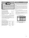
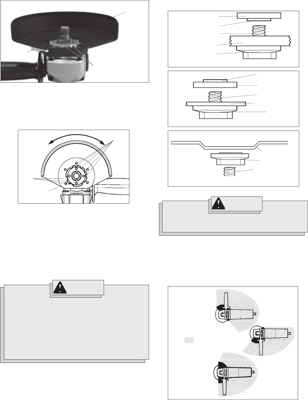
Fig. 12
Operator's Zones
WARNING!
To reduce the risk of injury when grinding:
ALWAYS use the proper guard.
ALWAYS properly install the guard.
ALWAYS hold the tool firmly with both hands using the
handles provided before and during grinding.
NEVER use a wheel that has been dropped.
NEVER bang grinding disc onto work.
NEVER grind without proper safety equipment.
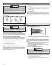
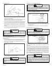
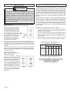
Installing, Removing and Adjusting the Guard (Cat. No. 6160-20)
(Fig. 7 & 8)
1. To remove the guard, unplug tool and place it upside down on a
level surface. Remove any accessories from spindle.
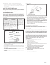
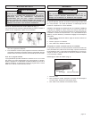
2. Press in the lock lever and rotate the guard to line up the tabs with
the slots, as shown (Fig. 8).
Fig. 7
Lock lever
Guard
Lock lever must
engage one of
five detents
This tool is shipped without the guard installed. The guard must be used
when using the tool as a grinder. The guard should be removed when
using tool as a sander.
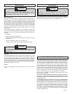
3. Press in the lock lever and lift the guard straight up and away from
the tool.
4. To install the guard, unplug the tool and place it upside down on a
level surface. Remove any accessories from the spindle.
5. Line up the tabs with the slots, as shown (Fig. 8).
6. Press in the lock lever and press the guard down onto the tool.
7. Press in the lock lever and rotate the guard clockwise to one of the
five detent slots. The lock lever must engage with one of the detent
slots.
8.To adjust the guard, press in the lock lever and rotate the guard to
one of the five detent slots (Fig. 8).
Fig. 8
Type 27 Reinforced 1/8" thick or less Cut-Off Wheels are suited for small
cut-off and shallow notching operations only.
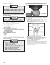
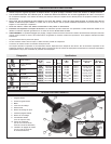
Installing Grinding Wheels (Fig. 9, 10, 11 & 12)
Lock lever
Ta b
slots
Detent
slots
Flange nut position for 1/8" thick or less wheels
Fig. 10
Boss
Flange nut
Spindle
Grinding wheel
Flange
Flange nut position for 1/4" thick wheels
Fig. 9
Flange nut
Boss
Spindle
Grinding wheel
Flange
Type 27 Grinding Wheel
Fig. 11
Spindle
Grinding wheel
Flange