


PAGE 12 — ESSICK FM9 — PARTS & OPERATION MANUAL — REV. #1 (03/12/01)
AIR SYSTEM
An air pulsation chamber is located on the left side of the unit.
The air is supplied to the chamber from the compressor. The
chamber is eouipped with an air pressure gauge and a safety
valve. The safety
valve is set at the factory at approximately 60
lbs.
HI-VOLUME PUMP
An outstanding feature of the ESSICK MODEL FM9 finishing
machine is that two different size pumps may be used, which
tremendously increases its versatility. A more powerful engine
and transmission are designed into this unit and a hi-volume
pump is furnished as standard. A lo-volume pump is offered as
an optional item. This pump consists of two parts: A smaller rotor
and a smaller stator, which, in turn, may be used when a lower
volume of material is required.
The installation of this pump is very easy because all parts are
interchangeable. It is only necessary to remove the rotor pin,
which fastens the rotor to the connecting rod located at the bottom
of the material hopper, and then thread out the stator tube with
the rotor encased, and install the lo-volume pump in the same
manner. The installation is made easier by threading the rotor
into the stator tube prior to starting assembly.
Fireproofing is one application where the hi-volume pump is of
great advantage. Competitive machines available for fireproofing
are twice the price of this versatile machine. Another purpose for
which the machine can be employed is the application of
browncoat. The hi-volume pump will apply approximately 14
sacks of gypsum hardwall material per hour.
To obtain maximum volume we suggest not to use more than 75
feet of 1-1/2" hose (actual pump volume is slightly under 2 c.f.m.).
PARTS LIST AND OPERATING INSTRUCTIONS
MODEL FM5E- I
THIS IS A SUPPLEMENT TO THE FM9 OPERATING AND
MAINTENANCE INSTRUCTIONS
READ BOTH SETS OF INSTRUCTIONS BEFORE
OPERATING THIS MACHINE
CAUTION: This machine uses high voltages that can be
dangerous and cause injury. Only qualified electricians should
install power supplies or service the electrical components. Power
supply must be in accordance with local electrical codes and of
adequate size to avoid the possibility of overheating the motors
due to low voltage. Supply line must be at least No. 8 gauge wire
and capable of delivering 35 amperes at 240 volts to control
panel of machine. When cleaning, never spray water on the
electric motor. Do not operate machine in standing water.
COMPRESSOR MOTOR - The 1H.P. compressor motor is
operated by a manual ON-OFF switch on the control panel.
PUMP MOTOR - The 5 H.P. pump motor is operated by a magnetic
starter switch. The magnetic starter is equipped with an overload
heater for motor protection.
A 240-volt system of switches and relays is used to control the
magnetic starter. It is protected by a circuit breaker with a reset
button in the door of the starter box
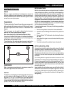
The air control sleeve valve on the nozzle is the master link in
the system. Connect the air line from the air compressor outlet to
the inlet on the control block next to the sleeve valve. This line
has air blowing out of it when the compressor is running. The
other air line runs from the sleeve valve to the pressure switch
inlet on the machine.
In operation, the sleeve valve operates the pressure switch. When
the sleeve valve is in the CLOSED position, air pressure is
applied to the pressure switch. This closes the switch and starts
the pump motor. When the sleeve valve is in the OPEN position,
air pressure is released from the pressure switch. This opens the
switch and stops the pump motor. The pump cannot be operated
without the air controls and air lines. This is a safety feature for
the gun operator and must not be bypassed in any way.
An AUTO-OFF-HAND switch is located on the door of the starter
box. Turning the switch to OFF overrides the sleeve valve control
and stops the pump. Turning the switch back to AUTO or HAND
returns control to the sleeve valve. This switch must never be
wired to turn the pump on without air pressure from the sleeve
valve to the pressure switch.
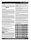
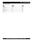
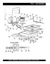
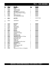
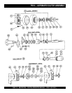
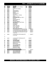
FER NOITPIRCSED ONLAIRES
TRAP
.ON
.YTQ
1 .P.H5–PMUP 303939 1
2
–ROTOMROSSERPMOC
.P.H2/11
960939 1
3
DNAROSSERPMOC
TROPPUSROTOM
127204 1
4
OTGNILPUOC–ESOHRIA
HCTIWSERUSSERP
115104 1
5 YLBMESSABAC 717204 1
6 ROTOMPMUP–YLLUP 862109 1
7 –HNIHSUBYELLUP
ROTOMPMUP
554109 1
8
-YELLUP
ROTOMROSSERPMOC
901109 1
9 HCTIWSERUSSERP 410049 1
01
ROTCENNOCDEGNALF
TELNI
450049 1
11 YDOBROTCENNOC 350049 1
21
RETRATSCITENGAM
DAOLREVOTUOHTIW
RETAEH
146049 1
31 HCTIWSROTCATNOC 800049 1
41 RETAEHDAOLREVO 142049 1
FM-9 — OPERATIONS