PAGE 18 — MQ-WHITEMAN FS1 CONCRETE SAW — PARTS & OPERATION MANUAL — REV. #3 (04/24/03)
CCC
FS 1 CONCRETE SAW — GENERAL INFORMATION
UNDER CARRIAGE SYSTEM
A jig welded heavy steel gauge under carriage chassis assembly
supports the saw in tracking, pivoting and stabilization. Two rear
wheels (8" x 2.0" x 3/4") and two front wheels (4" x 2.0" x 3/4")
supports the chassis. The entire assembly pivots about the rear
carriage and is lubricated through 90-degree grease fitting in
the rear axle tube. [See page 38, Under Carriage Assembly]
BLADE DRIVE SYSTEM
A rugged blade shaft assembly has been specifically designed
to support the optimum distribution of torque from the engine
shaft to the blade shaft, and to ensure minimal vibratory conditions
on the tips of the shaft. Balanced engine & blade shaft pulleys
are connected to their respective shafts. Two premium V-belts
connect the engine pulley to the blade shaft pulley. The 1-1/4"
diameter blade shaft is supported by two self-aligning pillow
block bearings, and is designed for left and right hand cutting.
[See page 40, Blade Shaft Assembly]
BLADE GUARD ASSEMBLY
The two-piece heavy gauge 14" blade guard is designed with a
water system to meet the challenges of wet cutting operations. A
fluted floodwater manifold assembly supplies optimum volume
and dispersal of water to both sides of the diamond blade for wet
cutting applications. The sizable (6") fluted tubes that direct the
floodwater resist clogging and are easily removed for
maintenance. The blade guard has a convenient "flip-up" front
cover for easy blade changes, and is spring tensioned for positive
up/down positioning. The blade guard may be oriented for left or
right hand cutting.
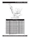
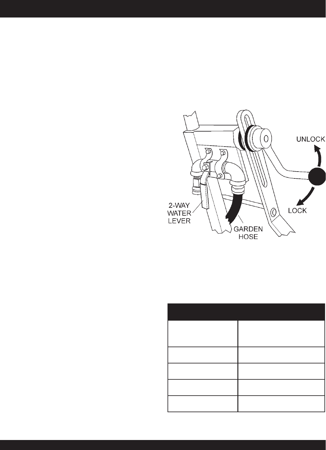
WATER SYSTEM
The FS1 Series employs a water system that provides floodwater
to the blade. Two 6" fluted tubes are connected via a manifold,
and are oriented inside the blade guard to provide optimum
water volume and dispersal to both sides of the blade. A standard
"garden hose" hookup valve connects the water source to the
saw, and a 2-way water lever (ON/OFF) is conveniently located
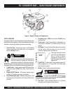
for the operator. [See Figure 6 and page 48]
MANUAL RAISE/LOWER SYSTEM
A positive locking mechanical raise and lower spring tension
assembly supports elevation cycling operations. A rotating ball
handle permits the engage/disengage process, and the tension
spring assists the operator with smooth blade entry and egress.
Blade orientation is referenced on the front face of the handle
bar support tube and is calibrated for 12", 14", 16" and 18"
diamond blades. [See Figure 11 and page 22]
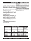
NOITCELESEDALB.4ELBAT
edalBdnomaiD
).nI(retemaiD
tuCfohtpeD
"21 "8/53
"41 "8/54
"61 "8/55
"81 "8/56
Figure 6. Water Connection/Manual/Raise Lower
Assembly


