PAGE 30 — MQ-WHITEMAN FS1 CONCRETE SAW — PARTS & OPERATION MANUAL — REV. #3 (04/24/03)
FS 1 CONCRETE SAW — MAINTENANCE
Blade Shaft Bearing Replacement
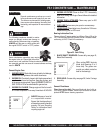
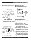
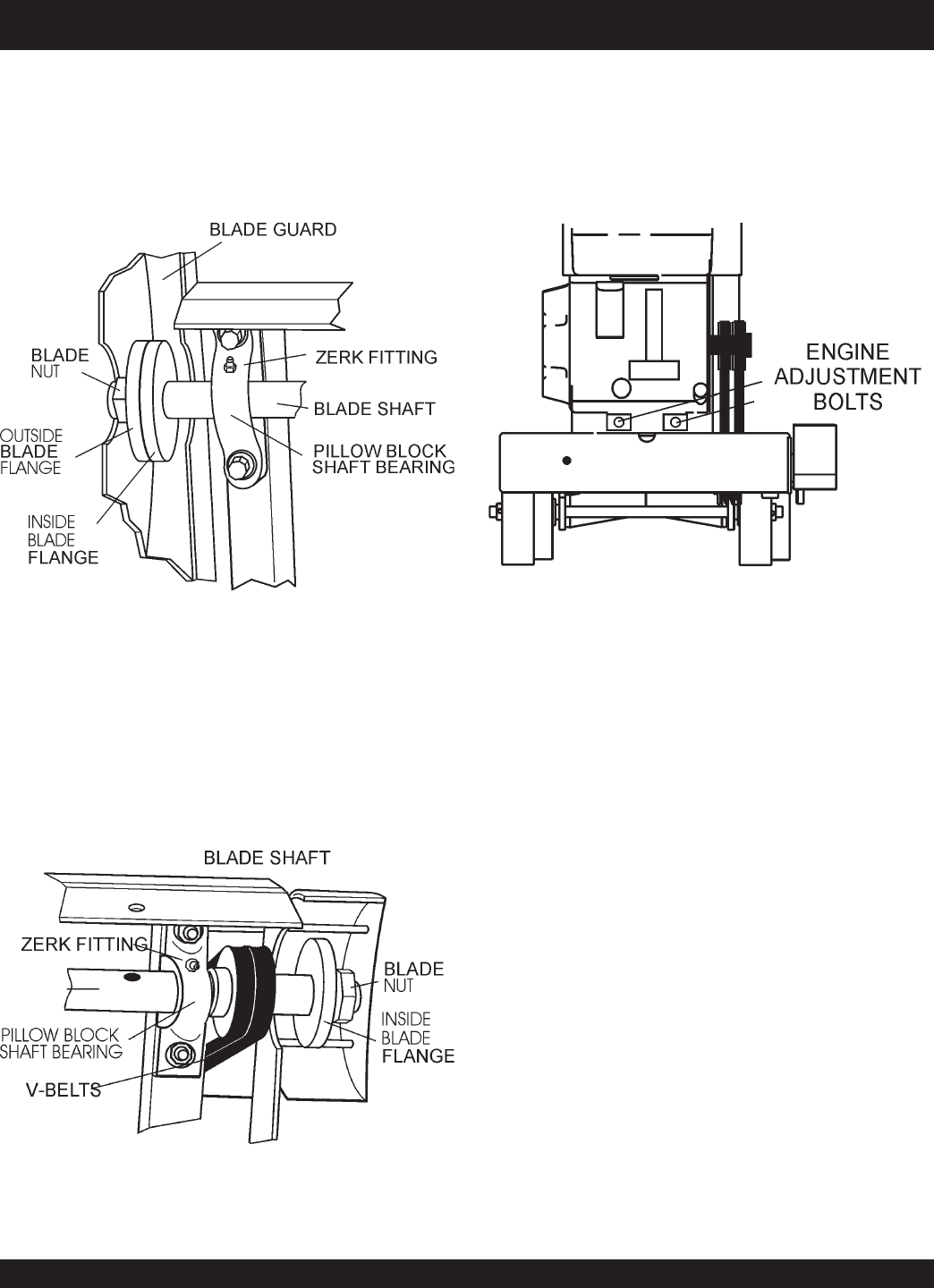
The FS 1 is supported by “tapped" base lock collar self-aligning
blade shaft bearings. These heavy duty bearings support the 1-
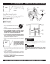
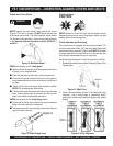
1/4 blade shaft, and have grease (zerk) points (Figures 24 and
25) conveniently located for service.
Figure 24. Right-Side Shaft Bearing
1.
Reference page 40 (Blade Shaft Assembly), during bearing
replacement.
2. Its recommended to replace both left & right hand bearings
collectively.
Figure 25. Left-Side Shaft Bearing
3.
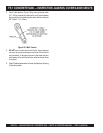
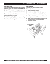
To loosen the tension on the two V-belts perform the follow-
ing:
z
Remove the V-belt cover (Figure 14).
z
Loosen the engine adjustment bolts (Figure 26).
z
Position the engine to allow for slack in the V-belts.
Replacement of the Blade Shaft Bearings
Perform the following to replace the "
blade shaft bearings
".
Reference Blade Shaft Assembly drawing, page 40:
4. Remove both the right and left hand blade shaft nuts from
the blade shaft.
5. Remove the blade flanges ( items 3 and 4)
6. Remove pulley set screw (item 8), and slide pulley (item
9 ) off blade shaft.
7. Remove (4) hex head cap screws (item 16) to free the
blade shaft assembly from the saw frame.
8. Remove the set screws from the pillow block bearing,
then slide the bearing(s) off the blade shaft.
9. Position the new blade shaft bearing(s) onto the blade
shaft and ensure that the bearing's zerk fitting is oriented
forward.
10. Re-install blade shaft nuts, pulley and blade shaft flanges
in the reverse order that they were removed.
11. Reposition the V-belts onto the blade shaft pulley, and
realign the V-belts for parallelism (Figure 15) as required.
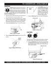
12. Tighten the V-belts by adjusting the engine adjustment
bolts.
13. Replace the V-belt cover guard.
Figure 26. V-Belt Adjustment


