


PAGE 22 —GB2000 BALLOON LIGHT• OPERATION AND PARTS MANUAL — REV. #3 (08/30/12)
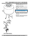
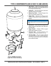
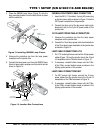
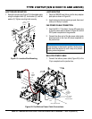
4. Place the GB2000 lamp fixture (Figure 13) onto the
lamp mounting bracket. Lock the lamp fixture in place
with the cotter pin.
Figure 13. Installing GB2000 Lamp Fixture
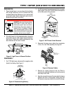
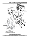
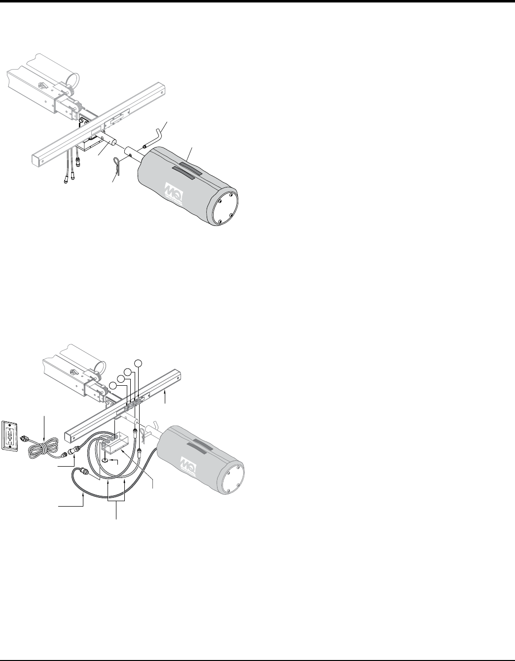
5. Unscrew the protective cap from the lamp power
receptacle on the junction box.
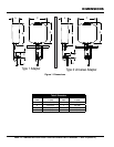
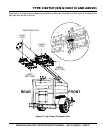
6. Connect the lamp power cord from the GB2000 lamp
fixture to lamp power receptace on the junction box as
shown in Figure 14.
Figure 14. Junction Box Connections
LB2000
LAMP FIXTURE
LOCKING
PIN
POLE ON
BRACKET
COTTER
PIN
10-PIN LAMP
POWER CABLE
T-BAR
JUNCTION
BOX
3-PIN LAMP
POWER CABLES
3-PIN
AC POWER
CABLE
FAN POWER
CABLE
GFCI
J4
J3
J2
J1
CAP
TYPE 1 SETUP (S/N G1900118 AND BELOW)
FAN/BALLOON POWER CABLE CONNECTION
1. Insert the 38 ft. (11.5 meters), 3-prong AC power plug
on the fan power cable as shown in Figure 14 into the
GFCI power receptacle on the generator.
2. Connect the other end of the fan power cable (quick
disconnect end) to the 3-pin AC power cable on the
junction box.
10-PIN LAMP POWER CABLE CONNECTION
1. Unscrew the protective cap from the lamp power
receptacle on the junction box.
2. Connect the 10-pin lamp power cable from the balloon
to the 10-pin lamp power receptacle on the junction box
as shown in Figure 14.
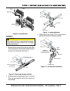
LAMP CABLE CONNECTIONS LT12
1. For LT12 series light towers connect the 2 lamp power
cables (Figure 14) from the junction box to the J3 and
J4 receptacles on the T-Bar as shown in Figure 14.
2. If necessary, reinstall bottom lamps onto the T-Bar.
At the T-Bar, connect bottom lamps as shown in the
lighting option section of this manual.
LAMP CABLE CONNECTIONS MLT
1. For MLT series light towers connect the 2 lamp
power cables from the junction box to the J3 and J4
receptacles on the T-Bar as shown in Figure 14.
2. If necessary, reinstall bottom lamps onto the T-Bar.
At the T-Bar, connect bottom lamps as shown in the
lighting option section of this manual.