


PAGE 28 — MQ-MIKASA MDR-9D VIBRATORY ROLLER — OPERATION AND PARTS MANUAL — REV. #0 (12/17/03)
MDR-9D — MAINTENANCE
HYDRAULIC OIL FILTER CHECK
1. The hydraulic oil filter should be replaced after first 25 hours
of operation.
2. After first replacement, it should be replaced after 250 hours
operation (2 months), every 500 hours of operation (4
months), and every 1,000 hours of operation thereafter.
3. When the suction resistance exceeds 254mmHg (oil
temperature in operation is 140 degrees F), replace filter.
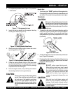
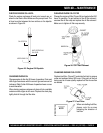
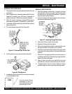
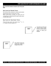
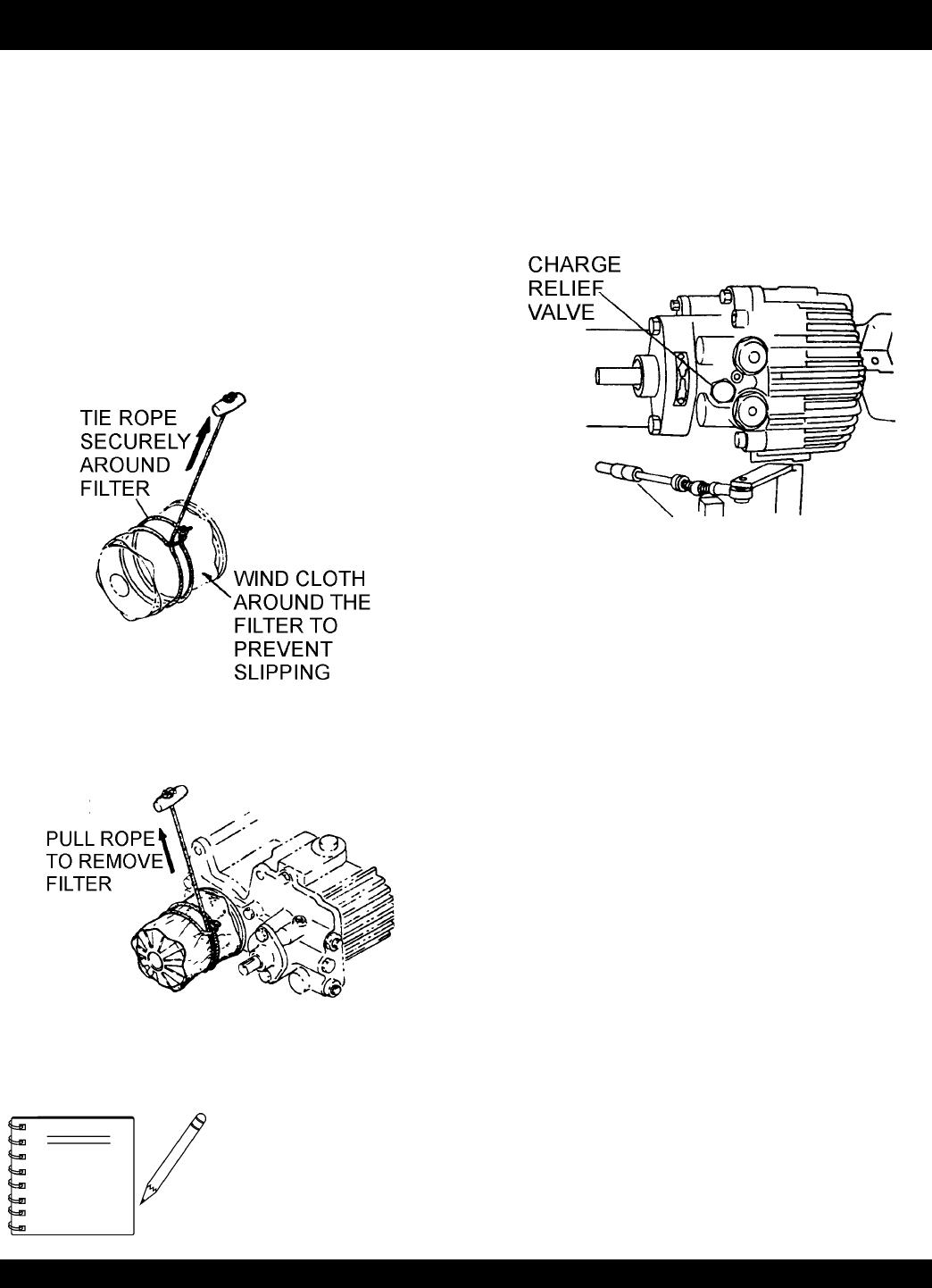
4. To remove the oil filter, wind a cloth around the filter to prevent
slipping (Figure 35).
5. Tie a rope securely around the filter (Figure 35).
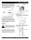
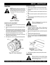
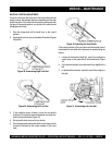
6. Forcibly pull the rope to remove the filter (Figure 36).
7. Immediately replace with new filter, screwing it on by hand
to avoid hydraulic oil leak.
Figure 35. Cloth and Rope Around Filter
Figure 36. Filter Removal
Use only genuine Mikasa
replacement oil filters (10
micron filter paper. Do not use
automobile-type oil filters.
NOTE
HDRAULIC AIR EXTRACTION
1. After filling hydraulic oil tank with oil, loosen the oil hose
joint and check that oil is enough to reach the oil suction
and outlet ports in the hydraulic transmission. Tighten the
hose joint securely after checking.
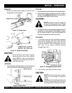
2. Loosen the charge relief valve located on the front side of
the hydraulic transmission (Figure 37).
3. Check that oil flows out from the valve hole.
4. Replace the charge relief valve tightly.
5. With the travel and vibrator levers in neutral position, start
the engine and idle at low speed for 3 to 5 minutes.
6. Check the forward and reverse rotation of the output shaft
by moving the travel lever slowly to its forward and reverse
positions.
7. Check the oil level gauge and make sure that there are no
air bubbles mixed in the oil. After checking, operate the roller
slowly at first then at full speed.
8. When oil level in the tank is low, replenish oil up to the
specified level, and screw the cap securely with a wrench.
9. If bubbles remain in the oil or foam is found, air is being
sucked through the suction side and should be checked.
Figure 37. Loosening Charge Relief Valve