


MP1 — OPERATION AND PARTS MANUAL — REV. #3 (03/29/10) — PAGE 17
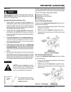
1. Ruler Backstop – When cutting, place material against
backstop. Use measurement rail (ruler) to determine where
material is to be cut.
2. Water Tray – When wet cutting is required, fill with clean
fresh water. Make sure submersible is totally immersed in
water.
3. Cutting Head Handle – Grab hold of this handle to move
the cutting blade head either
up
or down. To move the
cutting head, release the mounting plate release/lock lever.
4. Carrying Handle (Head) – Grip this handle (front) to lift
the mounting plate.
5. Blade Guard – Protects the user from the cutting blade.
NEVER
operate the saw with the blade guard removed.
6. Power ON/OFF Box – This box is used on
electric
models
saws only
. To turn on the saw place in the ON
position. Place in the OFF position to shut-down the saw.
7. V-belt Cover – Remove this cover to access the drive V-
belt.
NEVER
operate the saw with the V-belt cover removed.
8. Mounting Plate Release/Lock Lever – Push this lever
backwards to release
the mounting plate. This will allow
the cutting head to move either up or down. Push the lever
forward to lock
the mounting plate in place.
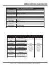
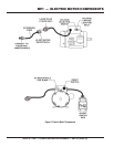
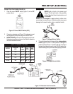
9. Electric Motor/Conduit Box– This unit uses 2 different
types of electric motors and voltages (see Table 2). Always
make sure the voltage selector switch has been set to the
correct position for the voltage being supplied to the motor.
Plug the water pump (electric models only) power cord
into the AC receptacle located on the conduit box.
10. Mounting Plate – Supports the electric motor/gasoline
engine. Plate has slotted holes for horizontal (right-side)
and vertical (left-side) adjustment of cutting head.
11. Carrying Handle (Head) – Grip this handle (rear) to lift
the mounting plate.
12 . Tie Rod – The tie rod length has been set at the factory for
best blade guard position for the majority of the cutting that
will be done.
13. Spring Tensioner – Allows for an easy up and down
movement of the mounting plate.
14. Mounting Plate Lock/Release Knobs – Turn knob (2)
clockwise to release the mounting plate. Turn counter-
clockwise to tighten.
15. Stopper – Place stopper in tray when filling with water.
16. Carrying Handle (Tray) – Grip this handle (right-side) to
trasport the saw.
17. Electric Water Pump – For best results place the pump
between the splash shield and the rear of the water tray.
This is for electric models only. Plug water pump power
cord into AC receptacle on electric motor conduit box.
NEVER
run pump dry. Pump must be immersed in water.
18. Spindle Bolt/Outside Blade Flange – When mounting
of the cutting blade is required, remove the spindle bolt
and outside blade flange. Align cutting blade with inside
flange arbor and reassemble spindle and outside blade
flange.
19. Splash Guard – Keeps water and debris from leaving the
water tray.
20. Carrying Handle (Tray) – Grip this handle (left-side) to
trasport the saw.
21. Mechanical Water Pump – This pump is used on gasoline
models only. Saw is shipped from the factor for wet cutting
applications (pump handle down). Place pump handle
upwards to disengage pump.
NEVER
run pump dry.
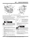
22. Engine – The gasoline model saws uses a 5.5 HP Honda
GX160, 4-stroke, OHV, single cylinder, air cooled gasoline
engine.
23. V-belt Cover (Gasoline Only) – Remove this cover to
access the engine shaft-side V-belt.
NEVER
operate the
saw with the V-belt cover removed.
24. Water Lines – Replace the clear vinyl tubing water lines
when they become brittle, worn or clogged. Water kits are
available through your dealer.
25. Priming Bulb – Squeeze this bulb to prime the mechanical
water pump (gasoline models only).
26. Blade Wrench – Use this tool to mount and remove cutting
blade.
27. Strainer – For best results place the strainer between the
splash shield and the rear of the water tray. This is for
gasoline models only.
NEVER
run pump dry. Strainer must
be immersed in water.
28. Miter Box – For angled cuts, place the lip of the miter box
on the measurement rail with the threaded thumb knob
facing you and tighten.
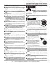
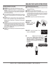
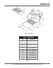
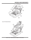
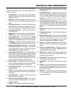
Figure 2 shows the location of the basic controls or components
for the MP1 saw. Listed below is a brief explanation of each
control or component.
CONTROLS AND COMPONENTS