


MP1 — OPERATION AND PARTS MANUAL — REV. #3 (03/29/10) — PAGE 31
MAINTENANCE (SAW)
CAUTION:CAUTION:
CAUTION:CAUTION:
CAUTION:
When loosening the handle lock, hold onto
the front of the motor/engine plate handle to
prevent the plate from raising rapidly, possible
causing the saw to become unstable. Let the
plate raise slowly. When removing the spring
from the pivot shaft, MAKE CERTAIN the motor/engine plate is
supported to prevent the cutting head from dropping.
13. Replace the spindle bearings as soon as they begin to make
any strange noises. Worn bearings can destroy blades very
quickly.
14. Grease pivot bearings periodically.
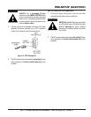
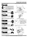
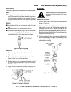
CUTTING HEAD ALIGNMENT (BLADE)
Make certain the
cutting head
is aligned properly. Misalignment
can adversely affect blade life. The motor/engine plate is slotted
so adjustment to the blade can be made as needed. The left side
has vertical slots, and the right side has horizontal slots. To adjust
the cutting head either vertical or horizontally perform the
following:
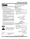
VERTICAL ADJUSTMENT
Remove the motor or engine from the mounting plate. Loosen
the pivot bearing bolts (2) on the left side of the mounting plate.
Move the pivot bearing to the extreme top of the slots in the
mounting plate. Thread a 3/8-16 bolt (adjusting bolt) down
through the hole in the top of the mounting plate. Tighten the bolt
against the bearing.
This will raise the mounting plate. Continue to tighten the bolt
until the blade is perpendicular to the conveyor cart. Tighten the
pivot bearing bolts. Remove the adjusting bolt and reassemble.
HORIZONTAL ADJUSTMENT
Loosen the pivot bearings (2) on the right-side of the mounting
plate. Slide the pivot bearing forward or backwards as needed,
until the blade is parallel with the conveyor cart. Tighten the pivot
bearing bolts.
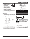
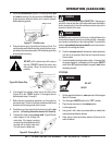
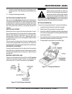
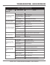
BEARING LUBRICATION CARE
There are two (2) grease points (Figure 30) for the MP1
gasoline
model saw. Use only Premium Lithium 12 based Grease,
conforming to NLG1 Grade #2 consistency. Grease
daily
.
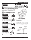
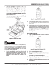
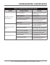
CUTTING HEAD REMOVAL
To remove the cutting head (Figure 31) perform the following:
1. Loosen the knobs (2) located on each side of uprights.
2. Slide the hooks (2) up and away from the pivot shaft.
3. Remove the handle lock that fastens the blade height adjusting
arm to the motor/engine plate. This is accomplished by simply
removing the cotter pin.
4. Disconnect the spring from the pivot shaft by raising the cutting
head until the tension is relieved from the spring.
5. To reassemble the cutting head, reverse these steps.
Figure 31. Cutting Head Removal
Figure 30. Zerk Fittings (Lubrication)