


R2000H RIDE-ON STATIC ROLLER — OPERATION & PARTS MANUAL — REV. #4 (07/24/08) — PAGE 27
R2000H — MAINTENANCE
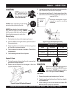
Brake Adjustment
1. The brake should be adjusted so that it takes 70 ± 5 lbs. of
force applied at the end of the lever to fully actuate it.
2. To adjust brake, turn the knob located at the top of the brake
lever clockwise (toward the operator) to tighten the brake.
3. Turn the knob counterclockwise (away from the operator) to
loosen the brake.
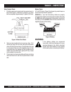
Steering Adjustment
1. The roller chain of the steering mechanism must be kept
clean, lightly oiled and properly tensioned.
2. Adjust the turnbuckle to allow 1/16" deflection to the slack
side of the chain when in the straight position.
Drive Chains
1. The drive chains must be kept clean, lightly-oiled, and
properly tensioned.
2. When wear of the side bars, rollers or sprockets become
noticeable, they should be replaced promptly.
3. Clean all dirt from the chain with solvent and re-oil lightly.
Drive Chains Tension Adjustment
1. Move the roller slowly in the reverse direction until the slack
side of the chain is toward the rear of the roller.
2. Put the control lever in the neutral position and shut the
engine off and apply parking brake.
3. Loosen the two bolts that hold the idler plate forward (into the
chain) using a pry bar.
4. Retighten the two mounting bolts.
5. Start the engine and move the roller in the forward direction,
5 to 10 feet.
6. Move the control lever to the neutral position and turn the
engine off.
7. Proper chain tension is approximately 0.2 to 0.4-inch deflec-
tion with approximately 5 lbs. of force applied to the center of
the span between the sprockets toward the front of the roller.
8. If the tension is still incorrect, readjust.
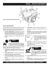
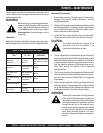
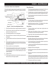
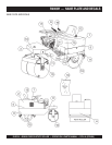
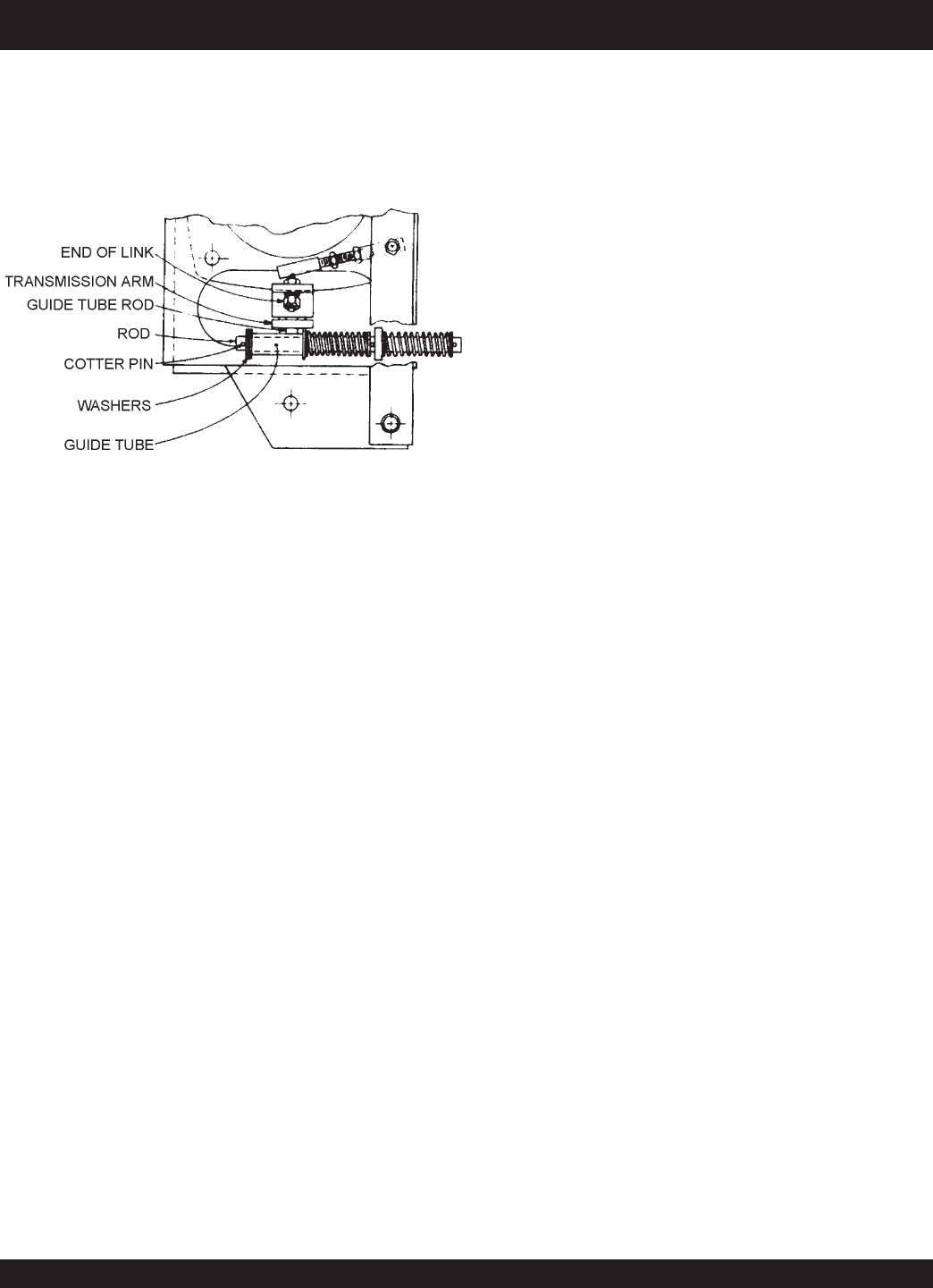
Transmission Control Lever Adjustment
If the roller tends to creep when the control lever is in neutral,
perform the following. Refer to Figure 21 for location of compo-
nents.
1. Place the unit where there is ample clearance fore and aft.
2. Open the cover, place the control lever to neutral position,
and remove cotter pin from rod.
3. Start engine and allow to run at idle speed.
4. Move control lever in reverse until roller just starts to move
backwards.
5. Carefully hold the control lever in place and turn the engine
off.
6. Without disturbing setting of control lever/transmission arm,
add washers on rod between cotter pin hole and grid tube
and replace cotter pin.
7. Return control lever to neutral position.
8. Check position of guide tube rod in arm slot. If not centered,
remove end of link from arm, loosen lock nuts, adjust length
by screwing ends in or out until ball stud drops in arm in
centered position.
9. Tighten all nuts.
10. Restart engine and make sure transmission output sprocket
does not move, at all engine speeds.
Figure 21. Control Lever Adjustment Points