


STX-SERIES • RIDE-ON POWER TROWEL — OPERATION MANUAL — REV. #1 (07/16/04) — PAGE 13
/02) — PAGE 13
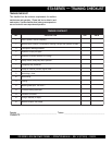
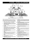
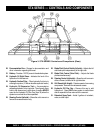
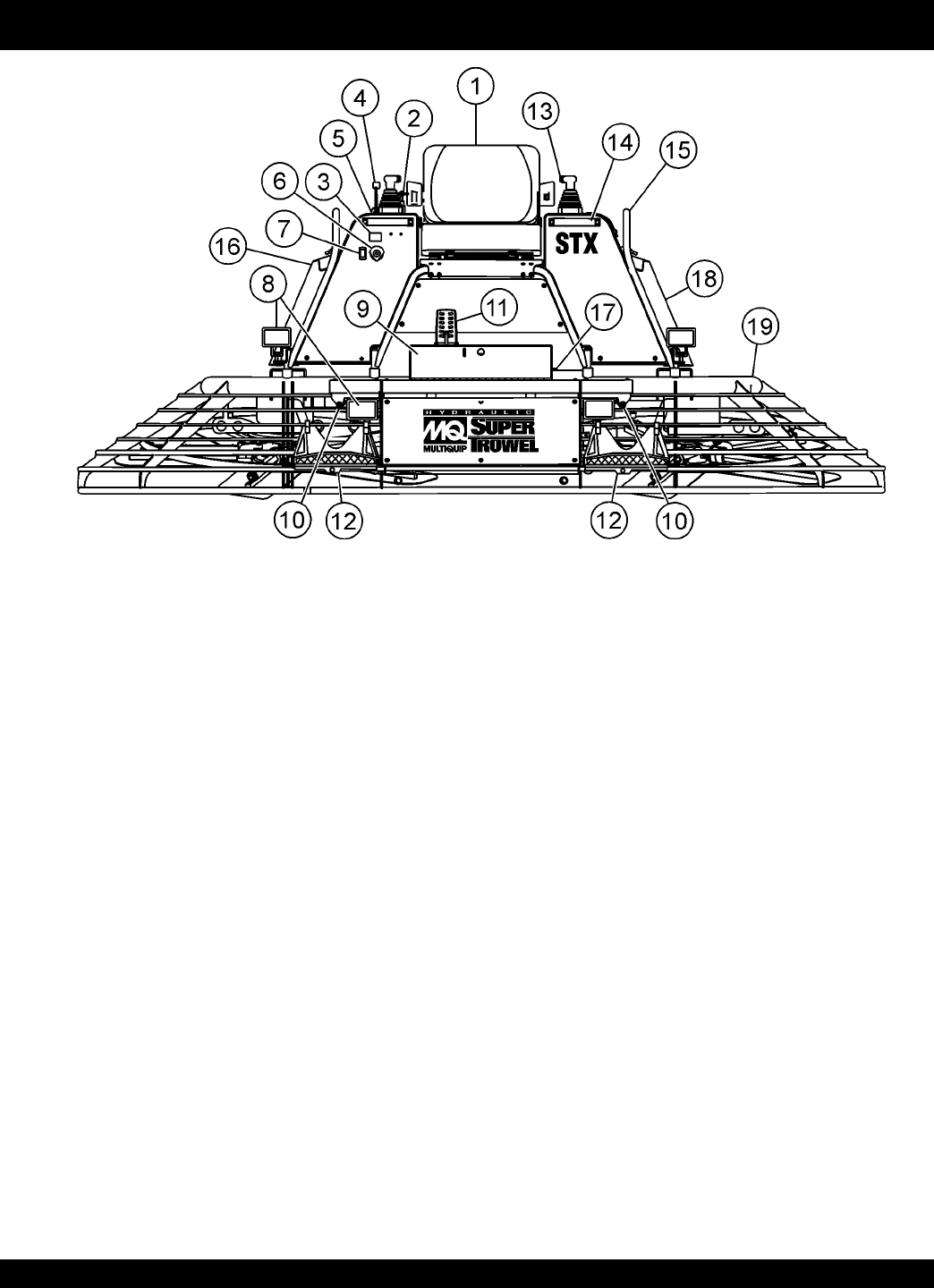
STX-SERIES — CONTROLS AND COMPONENTS
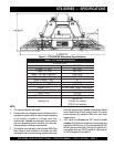
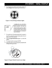
Figure 2. STX-SERIES Controls and Components (Front)
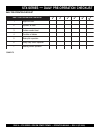
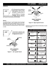
11. Foot Pedal – Controls blade speed. Slow blade speed is
accomplished by slightly depressing the foot pedal.
Maximum blade speed is accomplished by fully depressing
the foot pedal.
12. Removable Steps (left & right) – Provides for safe footing
for mounting and dismounting trowel. When removed,
provides access to spider and blade assemblies.
13. Retardant Spray Control Buttons (left & right) – When
pressed allows retardant spray to flow through the spray
nozzle located at the front of the machine.
14. Hand Holds – Use to assist safe mounting and dismounting
trowel.
15. Lift Loops – Located on both the left and right sides of the
main frame. Used when the trowel must be lifted onto a
concrete slab.
16. Pitch Block – (Behind grill guard.) Measure and adjust
pitch pressure at the pitch block.
17. Fuel Gauge/Filler Cap – Indicates the amount of fuel in
the fuel tank. Remove this cap to add fuel.
18. Overflow Bottle – (Behind grill guard.) Supplies water or
coolant to the radiator when radiator water or coolant level
is low. Fill to indicated level as shown on bottle.
19. Hydraulic Reservoir – Part of frame. Holds hydraulic oil
necessary for pump operation.
Figures 2 and 3 (pages 13 and 14) show the location of the
controls, indicators and general maintenance parts. The function
of each control, indicator or maintenance part is explained below:
1. Seat – Place for operator to sit. Trowel blades will not
rotate unless operator is seated. Seat is adjustable.
2. Trowel Speed Limiter Control – Used to adjust the
maximum trowel speed that can be obtained when the foot
pedal is fully depressed.
3. Hour Meter – Indicates number of hours machine has
been used.
4. Throttle Control Lever – Controls the speed of the engine.
Move the hand lever forward to increase engine speed
(high), backwards to decrease engine speed (low).
5. Operator Gauges – Allows operator to monitor engine,
hydraulic and electrical functions.
6. Ignition Switch – With key inserted turn clockwise to start
engine.
7. Light Switch – When activated, turns on six halogen lights.
Lights offer better visibility when working indoors.
8. Lights – Six low voltage halogen lights are provided with
this unit.
9. Toolbox Compartment – Storage for tools.
10. Spray Nozzles – Spray nozzle for retardant. Two spray
nozzles are supplied with this unit.