


PAGE 22 — STX-SERIES • RIDE-ON POWER TROWEL — OPERATION MANUAL — REV. #1 (07/16/04)
)
STX-SERIES — MAINTENANCE
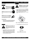
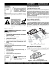
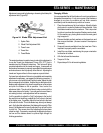
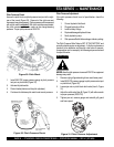
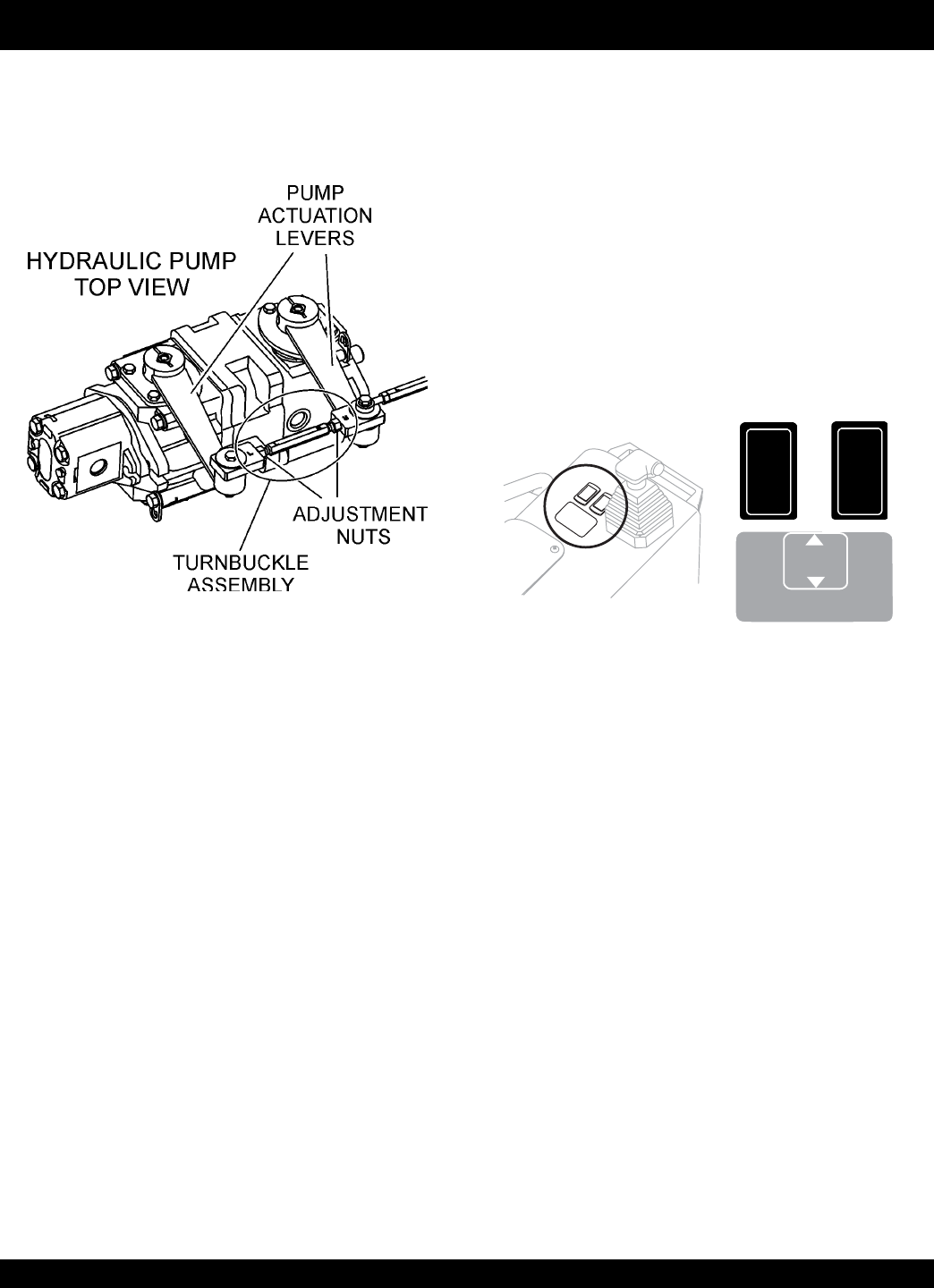
Figure 22. Turnbuckle & Adjustment Nuts
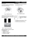
Matching Blade Pitch for Both Sets of Blades
Sometimes it may be necessary to match blade pitch between
the left and right sets of blades. There are some signs that this
may be necessary. For example, the differences in pitch can
cause a noticeable difference in finish quality between the left
and right sets of blades. The difference in blade pitch can also
make the machine difficult to control. This is due to the surface
area in contact with the concrete (the blade set with the greater
contact area tends to stick to the concrete more).
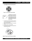
To synchronize pitch on both sides, the left blade assembly can
be pitched by itself. By using the electric blade pitch rocker
switches, (Figure 23) the pitch can be syncronized on the left
and the right sides.
■
Is the machine wearing out blades unevenly (i.e. one blade
is completely worn out while the others look new)?
■
Does the machine have a perceptible rolling or bouncing
motion when in use?
■
Look at the machine while it is running, do the guard rings
“rock up and down” relative to the ground?
Watch for the following indications when determining if blade
pitch adjustments are necessary:
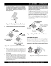
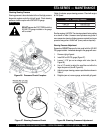
Blade Pitch Adjustment Procedure
The maintenance adjustment of blade pitch is an adjustment
that is made by a bolt (Figure 24) on the arm of the trowel blade
finger. This bolt is the contact point of the trowel arm to the lower
wear plate on the thrust collar. The goal of adjustment is to promote
consistent blade pitch and finishing quality.
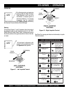
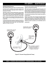
Figure 23. Blade Pitch Rocker Switches
LEFT
PITCH
ONLY
BLADES T O BE FLA T
WITH FLOAT PANS
TWIN
PITCH
LESSPITCH
MOREPITCH
This rod is basically a turnbuckle (Figure 22). Rotating it in one
direction increases the length and corresponding trowel speed.
Rotating it the opposite direction decreases the length and trowel
speed. The right side trowel speed should be within 3 rpm of the
left.
A good starting point in the adjustment process is to adjust the
rod such that both trowels begin to rotate at the same time when
the foot pedal is slowly depressed. This will, generally, get the
speeds fairly close; close enough for use if instrumentation is
unavailable (i.e. on the job site). From this point on, some form of
instrumentation is required to verify that the trowel speeds are
within tolerance. A strobe or magnetic pickup type speed indicator
is recommended to verify the speeds.
The trowel speeds should be adjusted on a dry concrete floor
with the blades pitched flat. Units with the John Deere
turbocharged engine should be set at 130-135 RPM with the
engine at full speed.