


PAGE 16 — TP24X TILE SAW • OPERATION AND PARTS MANUAL — REV. #2 (04/12/12)
ELECTRIC MOTOR COMPONENTS/SET-UP
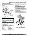
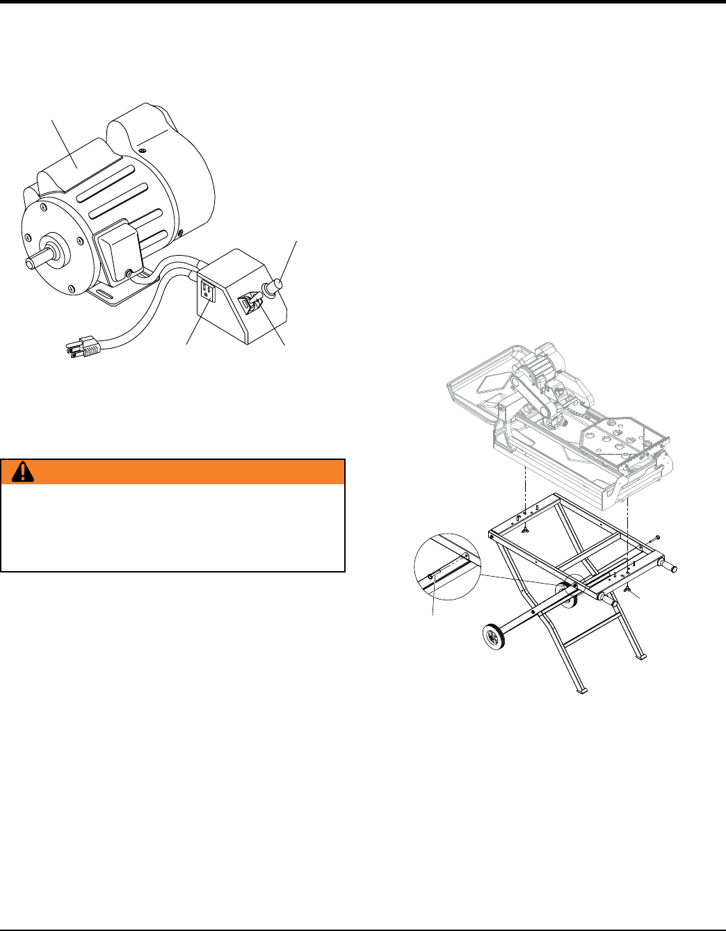
ELECTRIC MOTOR COMPONENTS
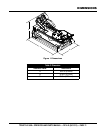
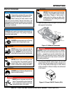
Figure 3 shows the location of the components of the
electric motor.
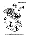
Figure 3. Electric Motor Components
SAW SET-UP
1. Open the shipping container carefully, lift the saw by
its carrying handles and place it on a suitable table or
platform. Make sure the table or platform can support
the weight of the saw.
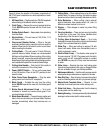
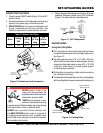
2. Make sure that the following items are found in the
container:
115V
ELECTRIC WATER
PUMPAC
RECEPTACLE
OVERCURRENT
BREAKER BUTTON
ELECTRIC
MOTOR
ON/OFF SWITCH
115 VAC, 60 Hz
SINGLE -PHASE
ELECTRIC MOTOR
WARNING
Whenever cleaning, adjusting or lubricating any part
of the saw, make certain to place the power ON/OFF
switch in the OFF position and disconnect the plug from
the power source.
3. If using the optional support stand, assemble as
described in the Support Stand Assembly section.
Make sure that the saw is secured on the support
stand as instructed.
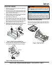
SUPPORT STAND ASSEMBLY (OPTIONAL)
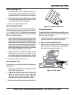
Refer to Figure 4 for location of components.
1. Remove the two lock pins inserted through the sides
of the stand. While holding the stand upright, spread
both sets of legs apart and swing the workbench over
and on top of the legs.
2. Insert lock pins through the legs and into the
workbench. After saw stand is completely assembled,
place the saw on top of the saw stand and secure the
saw frame in place by screwing the two knobs (one on
each side) under the saw frame.
Figure 4. Support Stand Assembly
LOCK PIN
WING BOLT
Saw
Water Tray
Drain Plug
Universal Wrench
Saw Blade
Water Pump
Rear Drip Tray
Owner’s Manual
MasterGuide Template
Base