


NI Spectral Measurements Toolkit User Guide 20 ni.com
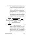
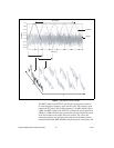
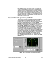
that is outside the effective band, the span changes to the default value,
which is the center of the effective band. Figure 7c demonstrates that if
you request a span that is wider than the effective band, the span decreases
until it falls entirely within the effective band without moving the center
frequency. Figure 7d demonstrates that if you enter center frequency and
span values that fall within acceptable limits but a portion of the span falls
outside the effective band, the center frequency moves until the span falls
entirely within the effective band.
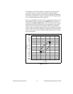
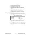
Resolution Bandwidth, Spectral Lines, and Window
The FFT process is equivalent to passing the time-domain signal through
a bank of bandpass filters with center frequencies that correspond to
frequencies of the FFT bins. The shape of the equivalent filter is determined
by the window applied to the time-domain signal. The
resolution
bandwidth
control represents the width of an equivalent filter corresponding
to a single FFT bin. You can specify this width in one of several ways
through the
RBW definition
parameter in the SMT configuration VIs. The
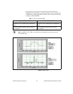
options are 3 dB, 6 dB, ENBW, and bin width. Both 3 dB and 6 dB define
the resolution bandwidth in terms of the distance between the two points
at which the filter response fell by the specified amount as compared to
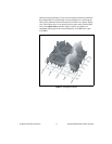
the peak response, as shown in Figure 8. Effective noise bandwidth (ENBW)
defines the resolution bandwidth as the bandwidth of an ideal rectangular
response filter, which has the same power output as the equivalent bandpass
filter for a given white noise input. Bin width defines the resolution
bandwidth as the distance from the center of one frequency bin to the
next—independent of the equivalent filter shape. The default value of
RBW
definition
is 3 dB.
Figure 8. Main and Side Lobes of a 7-Term Blackman-Harris Window