


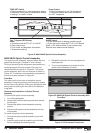

www.norcold.com/cda
52
Refrigerator Service ManualN6XX/N8XX Models
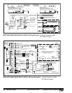
Backup Operating System
The Backup Operating System (BOS) allows cooling to
continue if the thermistor should fail. BOS is a duty
cycle operation. The duration of the cooling cycle can
be regulated by adjusting the temperature setting. The
higher the temperature setting number, the longer the
cooling cycle operates.
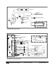
When the controls switch operation to BOS, the ON
LED flashes once every three seconds. The flowchart
on page 20 provides thermistor troubleshooting
information.
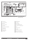
“Gas Lock-Out”
"Gas lock-out" prevents the controls from
automatically attempting to reignite the burner after the
controls have detected an ignition failure. "Gas lock-
out" may be caused by any or a combination of the
following:
n No LP gas available (empty LP gas tank).
n Incorrect LP gas pressure (LP gas pressure must
be 10.5 to 11.5 inches water column).
n Dirty burner.
n Clogged, damaged, or the wrong orifice.
n Incorrect electrode-to-burner air gap.
n A damaged or grounded spark/sense electrode
assembly.
n Damaged or inoperable gas valve.
To manually clear “Gas Lock-Out”:
n Turn OFF the refrigerator.
n Correct the no flame fault.
n Select AUTO or GAS operation.
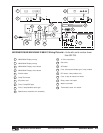
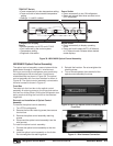
Modes of Operation
AUTO Mode
In AUTO mode, the controls automatically search for AC
power first. If AC power is present, the controls
automatically select AC operation. The selection of AC
power is indicated by the ON LED.
No AC Power
If AC power is not present or is interrupted, the controls
automatically switch to LP gas operation. When the
controls switch to LP gas operation, the GAS LED
illuminates and a 30 second trial for ignition period starts.
Both ON LED and GAS LED will remain illuminated. The
ON LED indicates the refrigerator is turned ON. The GAS
LED indicates the controls selected LP gas because AC
power is not available.
AC Power Restored
If AC power is restored the controls automatically revert
operation to AUTO AC and the GAS LED turns off. The
ON LED will remain illuminated to indicate AUTO AC
operation.
No AC and No Flame
If AC power is not present and a flame is not sensed after
the controls switch to LP gas, the flame sensing circuit
places the controls in "gas lock-out." In turn, the controls
command the ON LED and GAS LED to flash at one
second intervals.
The "A"/"no AC" flowchart on page 16 provides
information to troubleshoot no AC power faults.
The "F"/"no FL" flowchart on page 12 provides information
to troubleshoot no flame faults.
GAS Mode
In GAS mode, the controls will only select LP gas for
operation. GAS mode operation is monitored by the
flame sensing circuit. Normal GAS mode operation is
indicated by the GAS LED.
No Flame
In GAS mode, if a flame does not ignite during the 30
second trial for ignition, or the flame goes out, the
flame sensing circuit shuts off power to the gas valve
and places the controls in "gas lock-out." In turn, the
controls command the GAS LED to flash at one
second intervals.
The "F"/"no FL" flowchart on page 12 provides
information to troubleshoot no flame faults.