


13
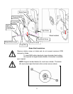
9. Attach the Blade Guard by sliding the Blade Guard Attachment Loop
over the Bayonet Mount, attach the Blade Guard Lock Pin, and close the
Hinged Blade Guard Nose.
10. Attach the Blade Guard by sliding the Blade Shaft Guard Attachment
Loop over the Blade Guard Bayonet Mount and then attach the Blade
Shaft Guard Lock Pin.
Multiple Mounted Blades:
Multiple mounted blades must be separated by a machined spacer. The
diameter of the spacer cannot be less than the diameter of the relieved blade
collars. The blade pin must pass through all blades and spacers, and seat itself
in the inside blade collar.
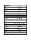
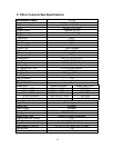
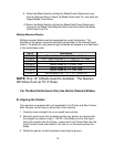
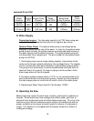
Part # Description
N1B0171 Guard, Blade 14” x 4-3/4” Wide 2” Stack
N1E0350 Collar Loose extended 4-1/4” Long (Cut To Length)
N1E0301
Spacer Blade φ8” x 0.03125 Thick
N1E0302
Spacer Blade φ8” x 0.0598 Thick
N1E0303
Spacer Blade φ8” x 0.1406 Thick
N1E0304
Spacer Blade φ8” x 0.1345 Thick
N1D0315 Bolt Extension 5/8”-11 x 7” (4” Thread) LH
NOTE: Only 14” A Blade Guard Is Available. The Spacers
Will Allow Cuts Up TO 3” Deep.
For The Best Performance Only Use Norton Diamond Blades
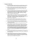
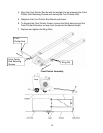
B. Aligning the Pointer:
This machine is equipped with an Expandable Front Pointer and Rear Pointer.
Both Pointers can be used on either side of the machine.
1. Carefully mark a straight line on a smooth level surface.
2. Move the machine so that the blade and the rear pointer are aligned with
the straight line drawn in step 1. NOTE: If the Blade is not on the same
side of the machine as the Pointer, remove the Front Pointer Rod from the
Front Pointer Frame and reattach it so that it is on the same side as the
Blade.
3. Rotate the pointer so that the wheel is touching the ground.