


Helpline No. UK / Northern Ireland 0870 7323023 • Rep. Ireland 1800 481005
Web Support: www.omegawolf.com/powercraft
Model Number:
PBF-1200 11
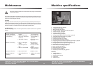
Assembly
• Slide the parallel fence onto the mounted rods until it is in full contact with
the workpiece. The zero-position is now set.
• Attach the ruler (17, Fig. C, page 5) to the rod of the parallel guide. The zero on
the ruler must be aligned with the zero mark (18, Fig. A1, page 4).
• Loosen the parallel fence fixing screw (4, Fig. C, page 5) and move the fence
until the desired setting has been reached. Important: when adjusting the pa-
rallel fence, please take into account the diameter of the cutter.
• Retighten the fixing screw (4, Fig. C, page 5).
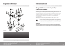
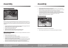
Mounting the guide bush
Fig. D
The guide bush is a handy aid for cutting a pattern.
• Mount the guide bush (23) on the router base (3) using the screws (22).
3
23
Helpline No. UK / Northern Ireland 0870 7323023 • Rep. Ireland 1800 481005
Web Support: www.omegawolf.com/powercraft
Model Number:
PBF-1200 10
Assembly
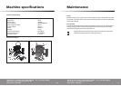
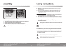
Mounting and removing cutters
Fig. B
Only use cutters with a shaft diameter which corresponds with the size of the col-
let. Only use cutters which are suited for the maximum speed of the machine. The
cutter diameter should not exceed the maximum diameter (see ‘Technical specifi-
cations’).
• Press the spindle lock (7) and turn the collet nut (6) until it engages in the lock.
Keep the spindle lock pressed during this procedure.
• Open the collet nut using the wrench.
• Place the cutter shaft in the collet.
• Tighten the collet nut so that the cutter is locked properly.
• Open the collet nut when you want to replace a cutter.
Adjusting the parallel fence r
uler
The parallel fence is a useful tool for precision routing at a fixed distance from the
edge of the workpiece.
• Place the desired cutter in the tool.
• Loosen the clamping lever (11, Fig A1, page 4).
• Push the tool down until the cutter sticks out from the base plate, then re-
tighten the clamping lever (11, Fig A1, page 4).
• Place the router onto the workpiece in such a manner that the cutter touches
the side of the workpiece. Please ensure that the furthest protruding part of
the cutter touches the workpiece (by turning the cutter if necessary).
• Slide the provided guide rods (20, Fig. C, page 5) into the appropriate holes.
7
6