


Page : 11
4
5
3
2
1
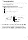
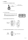
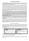
12.- INSTALLATION
1.- Prepare a panel cut-out with the dimensions indicated on paragraph 13.
2.- Slide the instrument (1) into the cut-out.
3.- Slide the two fixation pieces (3) with T shape by both lateral sides of the instrument, such as it
is shown on the drawing below.
4.- Turn the screw bolt until it is pressed firmly against the panel (4) and the instrument (1) remains
totally fixed.
5.- The front part of the instrument has the necessary elements to provide an IP 65 protection. If the
panel where this instrument must be installed, it must to comply some protection standards
against water splashes, then a rubber profile must be installed with a rectangular or round shape
(5) on the place indicated and shown on the drawing below.
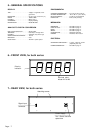
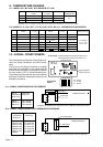
13.- MECHANICAL DIMENSIONS mm (inches)
D
E
A
B
C
DIMENSIONS PANEL CUT-OUT WEIGHT POWER
Digits Height A B C D E
4 57 (2.3) 264 (10.4) 120 (4.75) 112 (4.41) 256 (10.07) 112 (4.4) 2.3 Kg (5 lbs) 6 VA
4 100 (4) 480 (18.9) 180 (7.09) 112 (4.41) 472 (18.58) 172 (6.77) 5 Kg (11 lbs) 12 VA
Dimensions in mm. Values in brackets are inches or pounds.
Add 27 mm (1.1) to the dimension C for power connector.
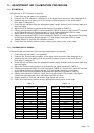
PANEL CUT-OUT
Panel thickness : Max. 14 (0.55)
Min. 2.5 (0.10)
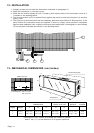
Aluminium back plate
Anti-Glare lens