


Page : 5
3.- MAIN FEATURES
On this paragraph is detailed the main features for every one of the series which are the following :
Instruments of four digits plus polarity (only minus) to show temperature using the signal generated by sensors
type RTD (PT-100 (0.00385), model MX) or Thermocouples (models J1,J2, K1,K2, T1,T2, E1,E2, S1,S2, R1,R2
and L1).
All instruments of these two series also has circuitry to linearize the sensor signal and the value displayed is
proportional to the measured temperature in °C or °F for all range corresponding to every sensor.
See paragraph 9, page 9.
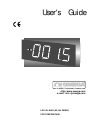
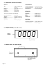
Serie LDP-124-XX : 4 digits type LED, seven segments, red or green colour with 57 mm (2.3") height and
minus sign for polarity.
Serie LDP-144-XX : 4 digits type LED, seven segments, red or green colour with 100 mm (4") height and
minus sign for polarity.
The complete reference for each instrument is obtained replacing the XX by the corresponding reference of
each temperature sensor.
The common features for all series are the following:
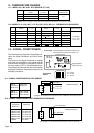
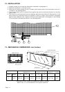
MECHANICAL.-
Housed in a rugged extruded aluminium profile housing for panel mounting or free standing.
Finished in anodized black colour. The frontal lens is mounted with a special rubber profile which
provides the front part of the unit with an IP-65 protection.
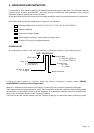
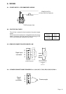
CONNECTIONS.-
Connections for Signal Inputs are made using one screw-clamp connector of four terminals located
on the rear part of the unit.
The recommended wire cross section for RTD sensors is 1 mm
2
.
For thermocouples must be used the compensate wire adequate for each thermocouple.
Connection for Power Supply uses a push-in cable connector with 2 terminals for power and 1
terminal for earth.
The fuse is located in the Power Supply socket, as well as the spare fuse.
SENSOR BREAK DETECTION.-
The linearizing circuits for RTD and for thermocouple sensors are provided with an special control to
detect when the sensor is broken or when the circuit sensor is opened.
If it occurs then the display starts to flash.
AUTOMATIC COMPENSATION.-
The variation resistance of the RTD sensors is in function of the temperature measured. To avoid
errors due to the lead wire resistance the LDP-1X4-MX uses a 3-wire measurement, which compensates
the lead wire resistance. However 2-wire sensors can be used. See wiring connections, paragraph 8.3
page 8.
The maximum resistance allowable is 10 Ω.
The thermocouple sensors generate a voltage produced by the junction of two metals with a different
characteristics. Therefore use the specific compensation wires for each model of thermocouple on
the measurement circuit to avoid create a new junction which should generate a small signal and it
should be added to the signal generated by the thermocouple sensor.
All instruments for thermocouple sensors are provided with a circuitry for Cold-Junction compensa-
tion.