


Page : 3
INSTALLATION
PRECAUTIONS.-
The installation and
the future use of this
unit must be done by
suitable qualified per-
sonnel. The unit has
not AC (mains)
switch, it will be in op-
eration as soon as
power is connected.
The installation must incorporate an external main switch.
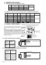
The unit has a protection fuse incorporated on the AC socket, if it
is necessary to change or replace, use the time-lag fuse according
IEC 127/2 and the values indicated below.
200 mA when the unit is operating at 230 Vac
400 mA when the unit is operating at 115 Vac.
Install also the necessary devices to protect the operator and the
process when using the unit to control a machine or process where
injury to personnel or damage to equipment or process, may occur as
a result of failure of the unit. See paragraph 8, WIRING.
SAFETY PRESCRIPTIONS.-
The unit has been designed and tested under EN 61010-1 rules and
is delivered in good condition. This operator's manual contains
useful information for electrical connections. Do not make wiring
signal changes or connections when
power is applied to the unit. Make signal
connections before power is applied
and, if reconnection is required, discon-
nect the AC (mains) power before such
wiring is attempted.
Install the unit in places with a good
ventilation to avoid the excessive heat-
ing. And far from electrical noise source
or magnetic field generators such as
power relays, electrical motors, speed controls etc...
The unit cannot be installed in open places. Do not use until the
installation is finished.
POWER SUPPLY.-
The power supply must be connected to the adequate terminals (see
the connection instructions). The characteristics of the power supply
are showed on the label on the rear part. Please make sure that the unit
is correctly connected to a power supply of the correct voltage and
frequency.
Do not use other power supply otherwise permanent damage may be
caused to the unit.
Do not connect the unit to power sources heavily loaded or to circuits
which power loads in cycle ON-OFF or to circuits which power
inductive loads.
SIGNAL WIRING.-
Certain considerations must be given when install the signal input and
control wires. If the wires are longs can act like an antenna and
introduce the electrical noise to the unit, therefore :
Do not install the signal input wires in the same conduit with power
lines, heaters, solenoids, SCR controls etc....and always far from
these elements.
When shielded wires are used, connect the shield to the common
terminal and leave unconnected the other end of the shield and do not
connect to the machine ground.
1.- IMPORTANT SAFETY CONSIDERATIONS
SAFETY CONSIDERATIONS
PRESCRIPTIONS.-
Before starting any operation of adjustment, replacement,
maintenance or repair, the unit must be disconnected from any kind
of power supply.
Keep the unit clean , to assure good functioning and performance.
Use for it a clean and humid rag. Do not use for the frontal lens
abrasive products, solvents, alcohol, etc... because its transparence
could be damaged and this may cause difficulty for a correct vision
of the reading.
To prevent electrical or fire hazard, do not expose the unit to
excessive moisture.
Do not operate the unit
in the presence of flam-
mable gases or fumes,
such as environment
constitutes a definite
safety hazard. The unit
is designed to be
mounted in a metal
panel.
If the unit shows signs of damage, or is not able to show the expected
measures, or has been stored in a bad conditions or a protection
failure can occur, then do not attempt to operate and keep the unit out
of service.
IN CASE OF FIRE
1.- Disconnect the unit from the power supply.
2.- Give the alarm according to the local rules.
3.- Switch off all the air conditioning devices.
4.- Attack the fire with carbonic snow, do not use water in any case.
WARNING : In closed areas do not use systems with
vaporized liquids.
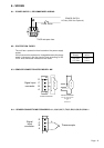
CONNECTIONS
All wiring connections are made using push-in cable connectors.
There is a separate connector block for power supply and input
signals. Please make sure that each connector block is connected on
the adequate place.
The wire cross section recommended for signal inputs is 1 mm
2
and
for power supply 2.5 mm
2
.
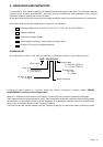
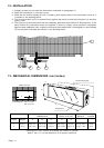
PANEL MOUNTING
Verify that the panel cut-out is correctly according to the dimensions
indicated on page 11 with a minimum depth of 150 mm. (5.9").
Install the fixation pieces in the lateral guides of the unit by its rear
part and then turn the screw firmly against the panel, until the unit is
totally hold on.
See paragraph 12 on page 11.