


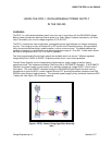

USING THE RPS-1in the OM-420
Omega Engineering Inc. 3 Stamford, CT
CONTROL INPUT
Two terminal connections are provided for connection of a low voltage power supply control signal. This
input signal controls the ON/OFF cycling of power supplies set to the AUTO mode. Typically, this control
input is controlled by a OM-320/420 Digital Output.
STATE-OF-CHARGE INDICATOR
When the TEST button is depressed, an approximate battery state of charge is displayed on the 10
position Display. This display is based on the battery voltage under a slight load.
INSTALLATION
MOUNTING
The RPS-1 should be mounted in a vertical position in order to optimize rain shedding and prevent direct
spray into the bottom fittings. The enclosure is designed for indoor and outdoor exposure within the
specified temperature limits. Battery life and capacity is at a maximum when the batteries are at a
temperature of 20C (68F). Shading from direct sunlight and/or insulation WITHOUT RESTRICTING AIR
FLOW AROUND THE UNIT can optimize battery life and capacity. During charging, the batteries will emit
small amounts of FLAMMABLE AND EXPLOSIVE HYDROGEN GAS. Additionally, heat is generated by
the voltage regulating circuits. For these two reasons, ventilation around the package will maximize
performance as well as minimize risk of potentially hazardous explosions.
WIRING
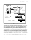
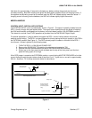
The OM-420 is factory configured to use OM-320/420 Digital Output #1 to control the RPS-1.
These connections are as follows: The positive Digital Output (Marked D01 on the TSA) is
connected to the RPS-1 positive CONTROL INPUT terminal.
The negative Digital Output (Marked GND on the TSA) is connected to the RPS-1 negative
CONTROL INPUT terminal. (See Figure 2)
Power Supply wiring should be routed through the liquid-tite fittings in the bottom of the OM-420 enclosure.
For most applications, 18 AWG wire will suffice without excessive voltage drop (18 AWG will result in less
than 0.1 V drop in 100 feet at 150 mA). PVC jacketed multi-conductor wire is a good choice that seals well
in the liquid-tite fittings.
OPERATION / SET-UP
POWER SUPPLIES
Select the desired output voltage for the A and B power supplies from the following table:
1 = 22 VDC
2 = 18 VDC
3 = 15 VDC
4 = 12 VDC
5 = 10 VDC
6 = 5 VDC
7 = 3.5 VDC
Set ONE of the seven VOLTAGE PROGRAMMING switches to the desired choice on each supply. If a
supply is not utilized, set all switches OFF (to the left). Correct voltage setting can be verified with a volt
meter reading from the OUTPUT terminal to the COMMON terminal. ONLY ONE voltage programming
switch should be ON for each supply.