


USING THE RPS-1in the OM-420
Omega Engineering Inc. 4 Stamford, CT
The MODE switch (bottom or eighth switch) should be set for the desired operation, AUTO or ON. AUTO
mode configures the supply to cycle ON and OFF per the state of the control signal coming from an
external device (OM-320/420). When the CONTROL INPUT signal (connected on the four position
terminal strip) is HIGH ( 5 VDC), either power supply configured in the AUTO MODE, turns ON. The ON
position configures the power supply to be continually outputting the selected voltage to the OUTPUT
terminals. The ON position is commonly used for set-up and troubleshooting of the sensor wiring.
The power supply outputs are internally current limited and protected from shorts. Current limiting occurs
at approximately 250 mA. If loads approaching this current level are connected, the output voltage should
be tested with a volt-meter to insure continued proper regulation. If the voltage is less than the OUTPUT
VOLTAGE SWITCH programmed setting, the power supply is in current limit mode and the current load
must be reduced. In many applications, this can be simply done by reprogramming the output voltage to
the next lower output voltage (providing the sensor will accept the lower level). The A and B power supply
OUTPUT terminals should NEVER be connected together.
The MAIN POWER SWITCH must be set in the 12VDC or the 24VDC position for the power supplies to
function. For optimum battery life, set the MAIN POWER SWITCH at 12VDC if neither power supply
21 1211109876543
21 1211109876543
Port 1
21 1211109876543
Port 2
R1 R2
DO2
DO3
DO1
GPDI Input
GND
Battery State of Charge
Indication
Power
Supply
Output
Com
mon
Charger
Input
Control
Input
+
_
4-20mA
Xmtr
5VDC Powered
Transducer
(mV Output)
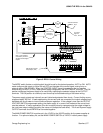
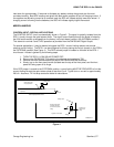
RPS-1 Power
OM-320/420 Terminal
Strip Adapter (TSA)
RPS-1 Power Supplies
Controlled by one of the
standard OM-420 Digital
Outputs.
mV Output
Signal to
Port 1, Chan A
4-20mA transmitter
output
to Port 1, Chan
B
Power
Supply
Output
Figure 3: RPS-1 Control Wiring