


USING THE RPS-1in the OM-420
Omega Engineering Inc. 6 Stamford, CT
held down for approximately 10 seconds to dissipate any battery surface charge and give the most
consistent reading. Best SOC readings are given with both power supplies off and no charging current. If
the supplies are delivering current to an external load, the SOC will indicate slightly lower than actual. If
charging current is flowing into the batteries, the SOC will indicate slightly higher than actual.
MISCELLANEOUS
CONTROL INPUT...SPECIAL APPLICATIONS
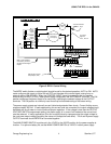
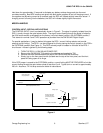
The CONTROL INPUT circuit is schematically shown in Figure 3. The signal is optically isolated from the
RPS-1 circuitry through the opto-isolator diode. The signal current flowing through the diode is limited by
the 8.2K series resistor as shipped from the factory (red circuit board jumper in the INTERNAL position).
This allows for nominal 0 and 5 VDC operation as provided from the OM-320/420 Digital Output.
For special applications, it may be desired to bypass the RPS-1 current limiting resistor and provide
external current limiting. The RPS-1 can be configured for this by placing the red pin jumper on the PCB in
the EXTERNAL position (See Figure 4). This RED colored jumper is located on the back of the RPS-1
circuit board. Access is gained by the following steps:
1. TURN THE RPS-1 & OM-320/420 POWER OFF,
2. Remove the OM-320/420 TSA retaining thumbscrew and unplug the TSA
3. Remove the three thumbscrews at the top of the OM-320/420-200 enclosure.
4. Slowly, tug on the front panel handle (located near the top of the front panel) and the front
panel will swing open on its hinge.
If this RED jumper is moved to the EXTERNAL position, current limiting MUST BE PROVIDED to limit the
current flowing through the opto-isolator diode to less than 5 mA. Typical turn-on current is approximately
200 uA. Assume a 1.2 Volt drop across the diode for calculations.
Position for NO
internal current
limiting
Shorting Jumper position
for internal current limit
(this is the factory default
setting)
Shorting Jumper
3 gold pins on circuit board
View of RPS-1 circuit board (front panel open)
Opto-Coupler
Shorting Jumper
8.2K Ohm Resistor
RPS-1 Control
Signal Input
Resistor limits current
through opto-isolator
Control Input Equivalent Circuit
hl200-03.ecw
Figure 4