


12
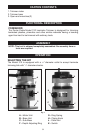
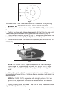
ASSEMBLING AND ADJUSTING BASE AND ROLLER (73100)
1. DISCONNECT TOOL FROM POWER SOURCE.
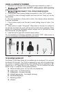
2. Remove power unit from base unit (see TO INSTALL BIT), and install the
bit.
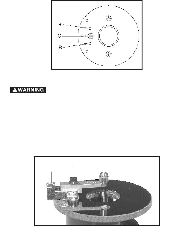
3. Position the base and roller guide assembly (A) Fig. 2, to the base unit.
The alignment pin on the back of the guide base fits into hole (C) Fig. 3.
4. Place the two mounting screws (F) Fig. 2, through the guide base and
thread into sub-base holes (B) Fig. 3. Tighten screws firmly.
5. Install motor to base and adjust bit exposure (see ADJUSTING BIT
EXPOSURE).
NOTE: For FLUSH CUTS, adjust bit exposure so that the straight
cutting edge (of bit) will engage the work. For BEVEL CUTS, adjust
bit exposure so that the angled cutting edge (of bit), will engage the
work.
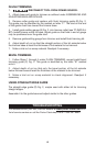
6. Align roller guide with bit by loosening locking screw (A) Fig. 4, and
turning adjusting screw (B) Fig. 4, (with hex wrench provided), until guide is in
desired location.
NOTE: For FLUSH CUTS, align roller with straight portion of bit. For
BEVEL CUTS, adjust roller to expose the desired amount of the bevel
bit.
7. Tighten locking screw and make a trial cut on scrap material to check
alignment. Readjust if necessary.
Fig. 4
A
B
Fig. 3