


14
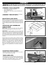
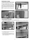
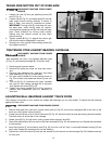
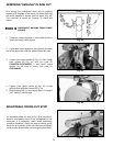
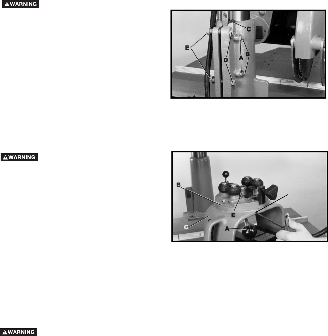
TAKING SIDE MOTION OUT OF OVER-ARM
1. Loosen hex nuts (A) and gib adjusting screws (B)
and (C) Fig. 31.
2. Loosen nuts (D) Fig. 31, and adjust bolts (E), so that
base wraps around column securely. If column is
tight in base, turn bolts (E) clockwise to loosen.
IMPORTANT: Turning bolts (E) clockwise will open
the base jaws, while turning bolts (E) counter-
clockwise and tightening nuts (D) will close the base
jaws. Check elevation by turning crank handle,
making sure the column moves up and down
without binding.
3. Tighten screws (B) Fig. 31, against the column gib
until all side motion disappears in over-arm.
4. Securely lock hex nuts (A) while holding screws (B)
and tighten screw (C).
Fig. 31
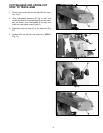
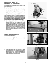
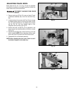
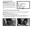
TIGHTENING YOKE AGAINST BEARING CARRIAGE
After extended use "play" may develop between yoke
(C) Fig. 32, and bearing carriage (B). To reduce "play":
1. Remove guard and saw blade.
2. Remove end plate and cross cut stop from track-
arm.
3. Remove yoke assembly from track-arm and place
yoke assembly (C) Fig. 32 on saw table.
4. Pull yoke clamp handle (A) to the position shown in
Fig. 32 to loosen, and loosen set screw (D) one turn
only.
5. Turn nut (E) Fig. 32 clockwise until "play" between
the yoke (C) and bearing carriage (B) is removed.
Then tighten set screw (D),Fig. 32
6. Tighten yoke clamp handle (A) Fig. 32 by moving it
forward, and reassemble yoke (C) assembly to
track-arm.
Fig. 32
D
DISCONNECT MACHINE FROM POWER
SOURCE.
DISCONNECT MACHINE FROM POWER
SOURCE.
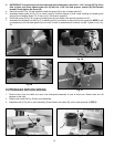
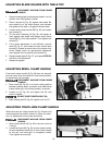
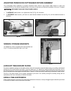
ADJUSTING BALL BEARINGS AGAINST TRACK RODS
The carriage is mounted on four double row, sealed ball bearings, two on fixed shafts. To adjust the ball bearings
against the track rods:
1. Remove end plate from track-arm, loosen clamp knob (A) Fig. 33, and move cuttinghead (B) to the front of the
track-arm, then tighten clamp knob (A).
2. Loosen two set screws, one of which is shown at (C) Fig. 33, that lock both front and rear bearing eccentric shafts.
The other screw is at the rear of the carriage.
3. Rotate yoke (B) Fig. 33 until hole in yoke is under either eccentric shaft (D).
4. Place roller head wrench (E) over hex nut (G) that locks shaft (D) Fig. 33, and loosen hex nut. Repeat this procedure
at rear bearing.
5. Insert hex wrench (F) into eccentric shaft (Fig. 33), and turn until all "play" is removed between bearing (D) and
track rods. Repeat this procedure for the rear bearing.
6. Tighten hex nuts with wrench (E) and lock set screws (C) with wrench at both bearings (Fig. 33). Replace end cap
on track-arm.
DISCONNECT MACHINE FROM POWER SOURCE.