


7
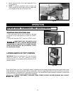
UNPACKING AND CLEANING
Carefully unpack the machine and all loose items from the shipping container(s). Remove the protective coating from
all unpainted surfaces. This coating may be removed with a soft cloth moistened with kerosene (do not use acetone,
gasoline or lacquer thinner for this purpose). After cleaning, cover the unpainted surfaces with a good quality household
floor paste wax.
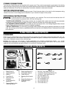
The following is an explanation of the operating controls of the Delta 14", 16" and 18" Radial Arm Saws. All users will
benefit by knowing how to set and operate the controls for all cutting operations. To avoid the possibility of damage
to the machine and/or injury to the operator, all user’s should become familiar with the operations and the controls
before turning the machine “ON’.
M
A
B
C
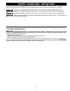
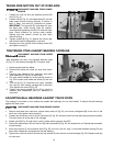
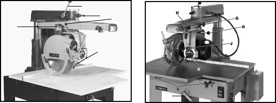
Fig. 2
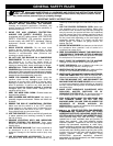
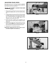
Fig. 3
E
F
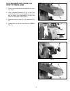
A - TRACK-ARM CLAMP HANDLE Fig. 2. Controls
swing of track-arm for all miter cutting operations.
Locks track-arm at any angle for the full 180° rotation.
To rotate track-arm, loosen clamp handle and rotate
arm. The arm will stop at the 0° and 45° positions right
and left. To move the arm past these points the track-
arm index knob (B) must be pulled out.
B - TRACK-ARM INDEX KNOB Fig. 2. Locates 0° and
45° miter position, right and left, of the track-arm
C - YOKE INDEX KNOB Fig. 2. Locates each 90°
position of the yoke for ripping or cross-cutting
operations. When rotating the yoke, the yoke clamp
handle (D) must first be loose.
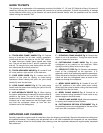
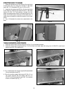
D - YOKE CLAMP HANDLE Fig. 3. The yoke clamp
handle must be loose when rotating the yoke to the rip
or cross-cut position.
E - ANTI-KICKBACK DEVICE Fig. 2. When ripping,
the yoke is positioned and clamped so that the blade is
parallel to the fence. The rear of the blade guard is
lowered until it almost touches the workpiece. The anti-
kickback rod is then lowered so that the fingers catch
and hold the workpiece. Never rip from the anti-
kickback end of the blade guard.
F - ELEVATING CRANK HANDLE Fig. 3. Controls the
depth of cut in all operations. Turning the crank handle
raises or lowers the over-arm.
G - CUTTINGHEAD CLAMP KNOB Fig. 3. Locks
cuttinghead at any position on the track-arm. When
ripping the cutting clamp knob must be tight.
H - CROSS-CUT STOP Fig. 3. Prevents unnecessary
travel of the cuttinghead on the track-arm. It is
especially useful when performing repetitive operations.
Clamp the stop to the side of the track-arm at a position
which will stop the cuttinghead travel as soon as the
blade cuts through the workpiece.
J - BEVEL INDEX KNOB Fig. 3. Locates 0° and 45°
and 90° positions of the motor when bevel cutting.
When tilting the motor for bevel cutting, the bevel clamp
handle (K) must first be loose.
K - BEVEL CLAMP HANDLE Fig. 3. Controls tilt of
motor for bevel cutting operations. Locks motor at any
desired angle on the bevel scale.
L - TABLE CLAMP KNOBS. Fig 3. Allows the operator
to quickly set the desired fence position.
M - CUTTINGHEAD RETURN ATTACHMENT Fig. 2.
Automatically returns the cuttinghead to the rear of the
track-arm after completion of the cut.
GUIDE TO PARTS