


15
Fig. 33
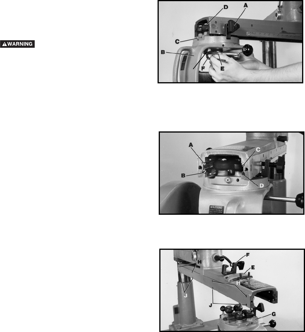
Fig. 34
G
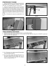
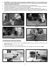
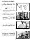
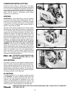
ADJUSTING TRACK RODS
Each track rod (A, B, C, D) Fig. 34 can be adjusted
individually to present a new bearing surface. Adjust the
track rods one at a time as follows:
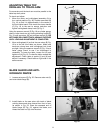
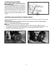
1. Remove end cap (E) Fig. 35, cross-cut stop (F) and
cutterhead assembly (G), from the track-arm (Fig.
35).
2. Loosen series of top screws (H) Fig. 35 just enough
to release holding action on the top left track rod (A)
Fig. 34. Insert screwdriver into slotted end of track
rod (A) Fig. 34, and turn slightly right or left.
Retighten all top screws (H) Fig. 35.
3. Bottom left track rod (B) Fig. 34 is adjusted in the
same manner by loosening series of bottom screws
(J) Fig. 35.
4. Adjust the right side track rods (C & D) Fig. 34 in the
same manner. NOTE: When adjusting bottom right
track rod (D) the rip scale must first be removed.
5. Reassemble the cutterhead assembly.
NOTE: After adjusting the track rods, check to see if
the blade is square to the table top.
Fig. 35
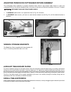
DISCONNECT MACHINE FROM POWER
SOURCE.