


16
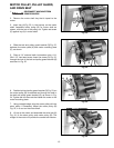
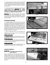
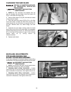
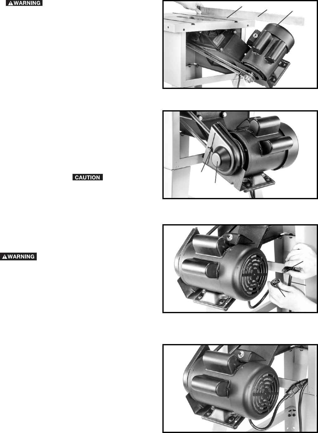
3. Fig. 28, illustrates the motor cord connected to the
switch assembly.
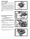
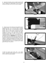
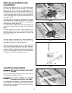
CONNECTING MOTOR CORD TO
SWITCH ASSEMBLY
1. DISCONNECT MACHINE FROM
POWER SOURCE.
2. Insert the pronged motor plug (A) Fig. 27, into the
female receptacle (B) of switch-to-motor cord (C).
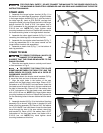
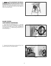
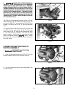
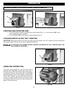
9. IMMEDIATELY AFTER ASSEMBLING
THE BELT, RAISE THE SAW BLADE TO ITS MAXIMUM
HEIGHT AND TILT THE SAW BLADE TO 45 DEGREES.
USING A STRAIGHT EDGE (L) FIG. 25, CHECK TO SEE IF
THE MOTOR END (J) FIG. 25, IS BELOW THE TOP OF THE
TABLE SURFACE (K). IF THE MOTOR END (J) IS ABOVE
THE TOP OF THE TABLE SURFACE, THE MOTOR MUST
BE MOVED TO THE LEFT UNTIL YOU ARE CERTAIN THE
TOP (J) OF THE MOTOR IS BELOW THE TOP OF THE
TABLE SURFACE. THEN RE-ALIGN THE MOTOR PULLEY
TO THE ARBOR PULLEY.
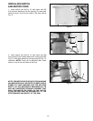
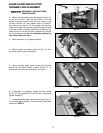
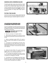
11. Align the hole in the outer cover (D) Fig. 26, with the
1/4-20x1-1/2" hex head screw (D) Fig. 23. Place the
outer cover (E) Fig. 23, onto the hex head screw. Place
a 1/4" external tooth lockwasher onto the hex head
screw, thread a 1/4-20 wing nut onto the hex head
screw, and tighten securely. Make certain
the outer cover does not interfere with the drive belt and
the motor pulley.
10. Place a 1/4" flat washer onto the 1/4-20x1-1/2" hex
head screw (D) Fig. 23. Place the spacer (F) Fig. 23,
onto the 1/4-20x1-1/2" hex head screw (D) Fig. 23, and
thread a 1/4-20 hex nut (E) Fig. 23, onto the hex head
screw.
Fig. 25
Fig. 26
D
E
Fig. 27
A
B
C
Fig. 28
K
L
J