


19
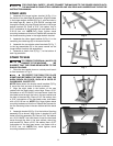
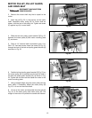
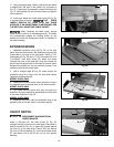
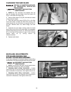
11. Using a straight edge, check to see if the saw blade
is aligned with the rear of the splitter (G), as shown in
Fig. 37. If alignment is necessary, loosen the screws (A)
Fig. 37, align splitter (G) with the saw blade, and tighten
two screws (A).
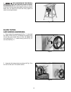
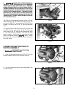
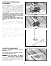
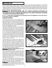
12. Lower saw blade and install table insert (P) Fig. 38,
in the saw table as shown. THE TABLE
INSERT SHOULD BE LEVEL WITH THE TABLE
SURFACE. IF AN ADJUSTMENT IS NECESSARY, SEE
THE SECTION “ADJUSTING TABLE INSERT”.
When installing the table insert, always
make certain to hold on to the blade guard (L). The insert
will automatically release the holding action on the
splitter and lower the blade guard when it is installed in
the table opening.
Fig. 37
G
A
Fig. 38
L
P
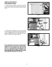
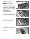
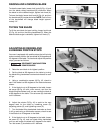
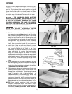
EXTENSION WINGS
1. Assemble extension wing (A) Fig. 39, to the saw
table. Align the three holes in the extension wing with the
three holes in the side of the saw table. Place a 7/16"
lockwasher (C) Fig. 39, then a 7/16" flat washer (D) on a
7/16-20x3/4" hex head screw (B). Insert the screw
through the hole in the extension wing and thread the
screw into the tapped hole in the side of the saw table.
Repeat this process for the two remaining holes in the
extension wing and the saw table.
2. With a straight edge (E) Fig. 39, make certain the
extension wing (A) is level with the saw table before
tightening three screws (B).
MODEL 36-649 ONLY
3. Assemble the other sheet metal extension wing to
the opposite end of the saw table in the same manner.
MODEL 36-678 ONL
Y
3. The model 36-678 comes with only one cast iron
extension wing and should be assembled to the left side
of the saw as shown in Fig. 39.
MODEL 36-679 ONLY
3. Assemble the other cast iron extension wing to the
opposite end of the saw table in the same manner.
Fig. 39
A
B
C
C
D
D
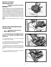
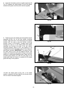
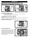
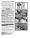
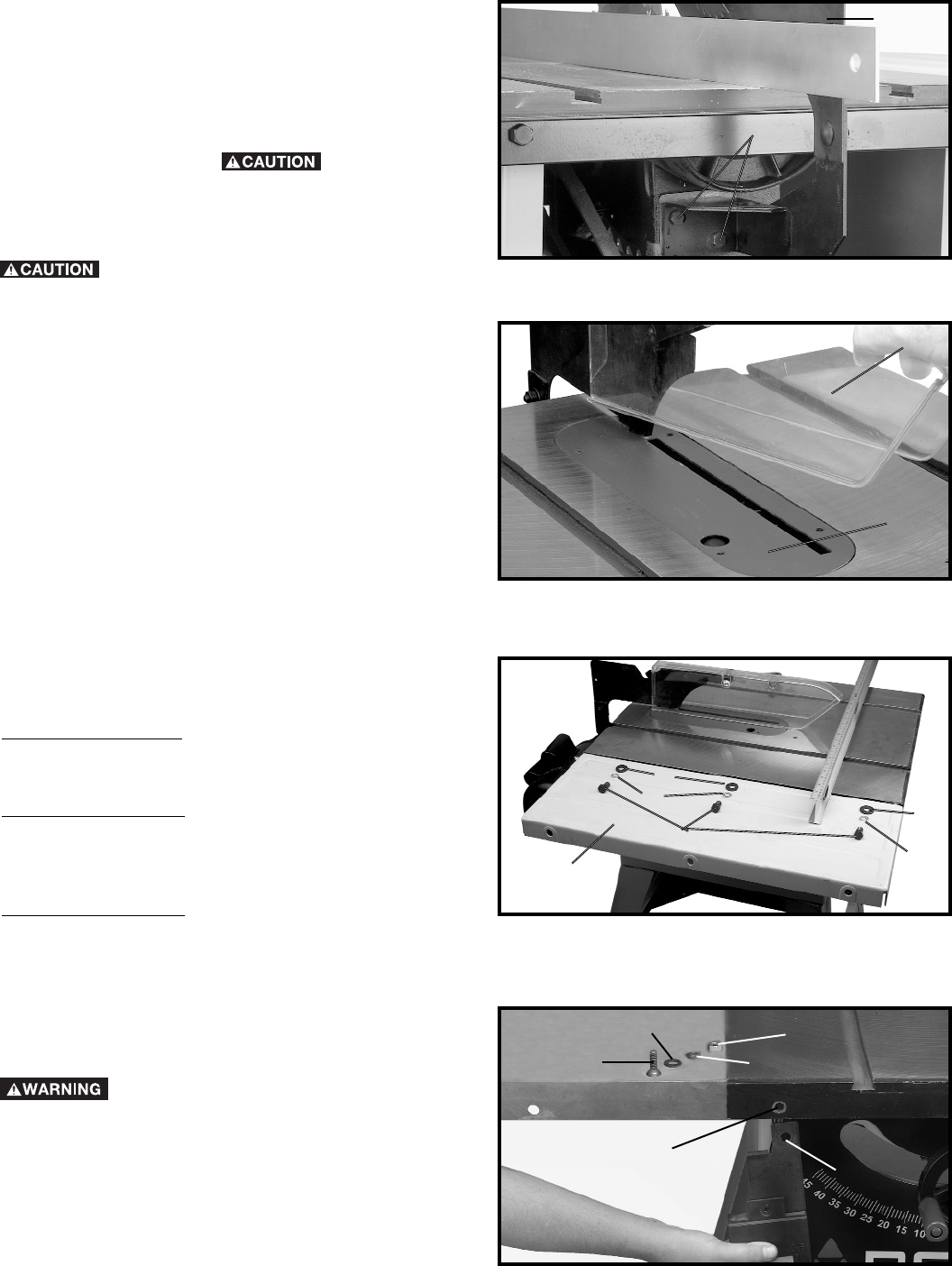
ON/OFF SWITCH
DISCONNECT MACHINE FROM
POWER SOURCE
Insert a 3/8-16x1-1/2" flat head screw (F) Fig. 40,
through hole (B) in the front the saw table. Place hole in
switch bracket (E) Fig. 40, on screw (B) located behind
the inner lip of the saw table. Place a 3/8" flat washer
(G), then a 3/8 lockwasher (H), onto the flat head screw
(F), and fasten with a 3/8-16 hex nut (J), and tighten
securely.
Fig. 40
F
B
E
G
H
J