


11
ADJUSTING 0 AND 45
DEGREE POSITIVE STOPS
Your saw is equipped with positive stops for rapid and
accurate positioning of the saw blade at 0 and 45
degrees to the table. This saw has the capability to go 2
degrees beyond 0 and 45 degrees (-2º to 47º). To adjust
the positive stops, proceed as follows:
1. DISCONNECT MACHINE FROM
POWER SOURCE.
2. Remove the blade guard and spreader assembly.
NOTE: SEE THE SECTION “REMOVING BLADE
GUARD/SPREADER ASSEMBLY.”
3. Raise the saw blade to its maximum height.
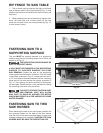
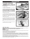
TO ADJUST POSITIVE STOP AT 0 DEGREES
4. Loosen the blade tilting lock handle, move the blade
tilting mechanism as far as possible to the left and
tighten the blade tilting lock handle.
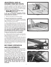
5. Place a square (A) Fig. 20, on the table with one end
of the square against the blade, as shown, and check to
see if the blade is at 90 degrees to the table. If it is not,
loosen screw (B) a few turns and move the blade tilting
mechanism until the blade measures 90 degrees to the
table. Then tighten blade tilting lock handle and tighten
screw (B) until it bottoms. NOTE: CHECK TO SEE IF THE
TILT INDICATOR POINTER POINTS TO THE ZERO
MARK ON THE SCALE. ADJUST IF NECESSARY.
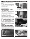
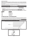
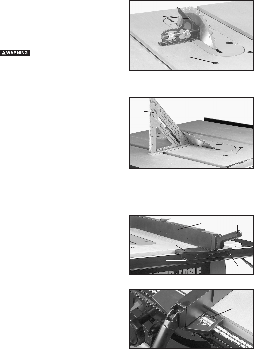
TO ADJUST POSITIVE STOP AT 45 DEGREES
6. Loosen the blade tilting lock handle, move the blade
tilting mechanism as far as possible to the right and
tighten the blade tilting lock handle.
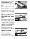
7. Place a square (A) Fig. 21, on the table with one end
of the square against the blade as shown, and check to
see if the blade is at 45 degrees to the table. If it is not,
loosen screw (C) a few turns and move the blade tilting
mechanism until the blade is at 45 degrees to the table.
Then tighten blade tilting lock handle and tighten screw
(C) until it bottoms.
Fig. 20
Fig. 21
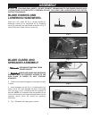
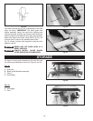
RIP FENCE OPERATION
AND ADJUSTMENTS
Fig. 22A
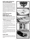
1. To move the rip fence (A) Fig. 22A, along the table,
lift up fence locking lever (B), slide the fence to the
desired location on the table and push down fence
locking lever (B) to lock the fence in position.
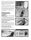
2. A pointer is supplied to indicate the distance the
fence is positioned away from the saw blade. If an
adjustment to the pointer (D) is required, loosen the
screws (C) Fig. 22B, that fasten the pointer window to
the fence head and adjust the pointer accordingly.
NOTE: THE RIP SCALE HAS TWO SETS OF
MEASUREMENTS DISPLAYED ON IT. THE TOP
SCALE IS USED WHEN THE RIP FENCE GUIDE RAIL
IS COLLAPSED. THE BOTTOM SCALE IS USED
WHEN THE RIP FENCE GUIDE RAIL IS FULLY
EXTENDED.
A
B
C
A
Fig. 22B
C
D
D
D
B
F
A