


8
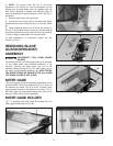
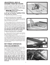
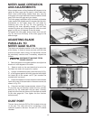
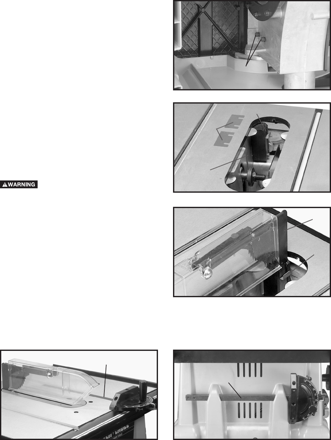
6. NOTE: The anchor block (B) Fig. 6, has been
adjusted at the factory so that the spreader will be
aligned with the saw blade which is supplied with the
saw. When changing to blades with different widths it
may be necessary to adjust the anchor block (B) Fig. 9,
as follows:
7. Remove table insert and saw blade.
8. Loosen the two screws (C) Fig. 8 (under saw table),
that attach the anchor block (B) Fig. 9, to the saw frame
(E).
9. Three additional shims, two of which are shown at
(D) Fig. 9, are supplied with your saw and can be used as
required between the anchor block (B) and the frame (E)
in order to align the spreader with the saw blade.
10. After adjustment is completed, tighten the two
screws (C) Fig. 8.
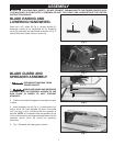
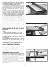
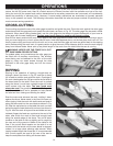
REMOVING BLADE
GUARD/SPREADER
ASSEMBLY
DISCONNECT TOOL FROM POWER
SOURCE.
The blade must be in the 90 degree position to the table
for the blade guard and spreader assembly to be
removed. Remove the table insert, pull out on the
spreader release spring (A) Fig. 9A, while pulling up on
the blade guard/spreader assembly (B). NOTE: STORE
THE BLADE GUARD AS SHOWN IN FIG. 31A, WHEN
THE BLADE GUARD IS NOT IN USE.
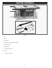
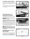
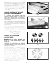
MITER GAGE
The miter gage is shipped completely assembled and is
supplied with a T-slot miter gage bar (A) Fig. 10, that can
be inserted into either one of the two T-slotted miter
gage grooves located in the table top, as shown. The T-
slot miter gage can be extended beyond the front of the
table for cross-cutting wide workpieces.
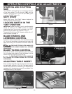
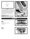
MITER GAGE HOLDER
Fig. 11, illustrates the miter gage (D) inserted into the
miter gage holder when not in use.
Fig. 8
Fig. 9
Fig. 10
Fig. 11
A
C
D
Fig. 9A
A
B
D
E
B