


12
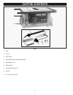
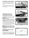
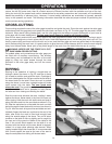
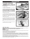
RIPPING THIN STOCK
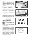
To adjust the fence, pull up on lever (B) so that the top of
the rip fence can be removed, and repositioned on the
rip fence as shown in Fig. 25. This is only necessary
when the fence guide rails are extended.
When using the guide rails for ripping, the fence must be
positioned as shown in Fig. 25, so that the wood can rest
on the ledge (C,) up against the rip fence.
An auxiliary wood insert can be placed in the gap
between the saw table and the rip fence extension to
add extra support.
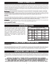
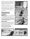
Fig. 24
Fig. 25
B
C
A
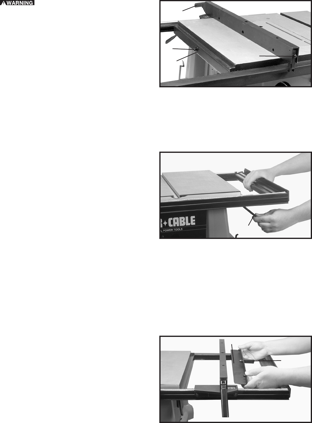
RIP FENCE EXTENSION
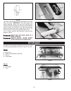
The saw has the capability to increase its ripping
capacity by extending the rip fence guide rails.
To extend the rip fence guide rails pull lever (A) Fig. 24,
to the right, and pull out on the guide rails. Then lock the
extended rails.
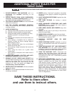
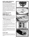
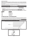
REPLACING THE RIP FENCE
SCALE
A metric scale can be attached to the rip fence as
follows:
1. Extend the rip fence guide rail as far as it will go.
2. Use a pencil and “mark” the guide rail at the “0”
location of the scale and remove the standard scale.
3. Place the metric scale on the guide rail referencing the
“0” mark.
4. Collapse the guide rail and check to see if the “0”
mark is accurate.
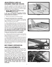
5. If an adjustment is necessary, adjust the “0” mark by
loosening nut (G) Fig. 23, and turning screw (H)
clockwise to move the “0” mark to the left, and counter
clockwise to move the “0” mark to the right, once the “0”
is set properly on the rip fence guide rail, turn nut (G)
counterclockwise to lock nut (G) against screw (H).
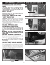
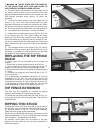
3. THE RIP FENCE MUST BE PARALLEL
TO THE MITER GAGE SLOT AND SAW BLADE TO
HELP PREVENT KICKBACK WHEN RIPPING.
4. The saw blade is set parallel to the miter gage slot at
the factory and the fence must be parallel to the miter
gage slot and saw blade in order to do accurate work and
help prevent kickback when ripping. To check the
alignment:
5. Position the fence close to the miter gage slot, as
shown in Fig. 22A. Push fence toward saw to insure
alignment screws are in contact with the fence rail. Clamp
the fence to the table by pushing down the locking lever
(B). The fence should be parallel with the miter gage slot.
6. If an adjustment is necessary, proceed as follows:
7. Loosen the two screws and jam nuts (D) Fig. 22A, and
lift up locking lever (B). Then while holding the fence
bracket (F) Fig. 22A firmly toward the rear, move the rear
end of the fence (A), by adjusting the two screws (D) until
the fence is parallel with the miter gage slot. Then push
down locking lever (B). Tighten jam nuts (D) on adjusting
screws.
8. The clamping action of the fence (A) Fig. 23, can be
adjusted by lifting up locking lever (B) and turning nut (E)
clockwise to increase or counterclockwise to decrease
the tension of the clamping action of the fence.
Fig. 23
B
H
G
E