


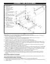
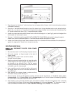
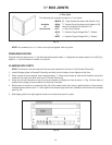
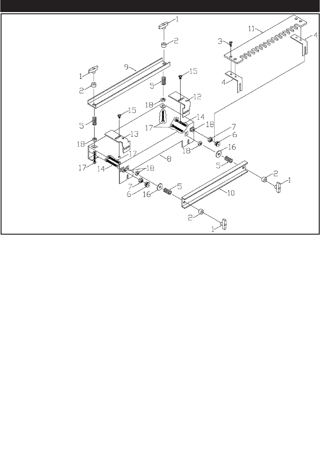
NOTE: Refer to Fig. 1 for the various parts of the Model 4112 Dovetail Fixture/Jig.
1. Insert jam nuts, item 18, into each of the outside recessed areas on front of the base, item 8. Thread bolts,
item 14, into each jam nut and tighten firmly.
2. Insert the remaining jam nuts, item 18, into the remaining recessed areas on the front and top of
base, item 8. Thread bolt, item 17, into jam nut and tighten firmly.
3. Thread locknuts, item 7, on bolts, item 14 up to the jam nuts and tighten firmly.
4. Thread on knurled nuts, item 6, on bolts, item 14 up to the locknuts and tighten firmly.
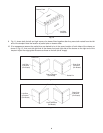
5. Select the edge guide to be used, either #1 for half-blind dovetails or #2 half-blind rabbeted dovetails. Place
right and left edge guides, items 12 and 13, on base, item 8, and assemble with screws, item 15. Slide edge
guides to end of base. Do not tighten at this time.
6. To install top clamp bar item 9, place springs item 5 on bolts, item 17, followed by the top clamp bar then
spacers, item 2. Retain assembly with clamp knobs, item 1.
6A.To install front clamp bar item 10, place washers item 16 (used on front bar only) on bolts item 17. Add springs
item 5, on bolts, item 17, followed by the front clamp bar then spacers, item 2. Retain assembly with clamp
knobs, item 1. NOTE: When clamping material thicker than ¾", the spacers, item 2, will need to be removed.
7. Attach templet, item 11, to templet brackets, item 4, with templet retaining screws, item 3.
8. Insert assembled templet between Iocknuts, item 7, and knurled nuts, item 6.
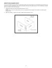
9. The completely assembled Dovetail Fixture/Jig should be securely mounted to a sturdy bench or stand to
prevent movement during routing operations. Slots are provided in the front and back of the base for this
purpose.
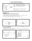
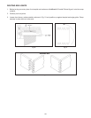
ADJUSTING TEMPLET LOCATION
Front to back positioning of the templets is accomplished by varying the location of the locknuts (item 7, Fig. 1).
ADJUSTING EDGE GUIDE LOCATION
1. Remove templet from Dovetail Fixture/Jig. NOTE: DO NOT UNCLAMP DRAWER FRONT.
2. Loosen edge guide retaining screw, (item 15, Fig. 1) and slide edge guide to drawer front and secure in place.
3. Replace templet.
Fig. 1
ASSEMBLY AND ADJUSTMENT
1. Clamp Knobs (4)
2. Spacers (4)
3. 10-32 x .375 Socket
Head Screws (4)
4. Templet Brackets (2)
5. Springs (4)
6. 1/4-20 Knurled Nuts (2)
7. 1/4-20 Lock Nuts (2)
8. Base
9. Top Clamp Bar (Long)
10. Front Clamp Bar (Short)
11. Templet
12. Right Edge Guide
(One #1 & One #2)
13. Left Edge Guide
(One #1 & One #2)
14. 1/4-20 x 1.5" Bolt (2)
15. 10-32 x .375 Pan Head
Screw (2)
16. 1/4 Washer (2)
17. 1/4-20 x 1.75" Bolt (4)
18. 1/4-20 Jam Nut (6)
4