


17
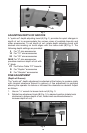
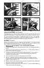
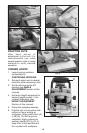
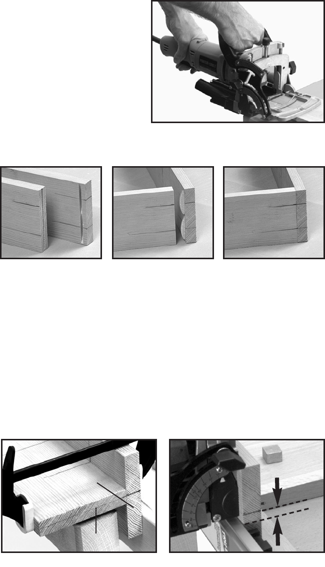
7. Hold tool firmly as shown in
Fig. 21, squeeze trigger switch to
start tool.
8. At a slow, steady pace, push
tool forward in base as far as
depth stop allows.
9. Release trigger switch to
stop tool and remove tool from
work.
10. Repeat steps 6 through 9
until all the grooves for this joint
are completed.
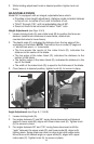
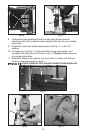
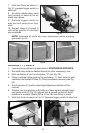
NOTE: Assemble all joints and verify alignments before applying
glue (see Fig. 22).
SURFACE (“T”) JOINTS
1. Layout groove positions as described in POSITIONING GROOVES.
2. Set depth stop turret to desired biscuit (or other accessory), size.
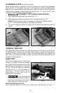
3. Mark centerline of joint on workpiece “A” (see Fig. 23).
4. Clamp a straight edge guide to the workpiece,
3
/8" back from the joint
centerline (as marked in Step 2). Clamp workpiece securely (see Fig.
24).
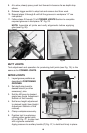
5. Set tilt fence to 0° position (see Angle Adjustment Section of this
manual).
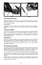
6. Position tool to workpiece with bottom of base against straight edge
and guide notch (C) Fig. 25, aligned with a groove centerline. Apply
pressure to auxiliary handle (D) Fig. 25 to hold tool firmly in place.
7. Hold tool firmly as shown in Fig. 21. Squeeze trigger switch to start tool.
Fig. 22
Fig. 21
Fig. 23 Fig. 24
A
B
3
/8
"