


13
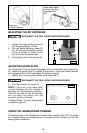
USING STRAIGHT EDGE GUIDE
You can use the straight edge guide (D) Fig. 5 with either bit for trimming straight
edges.
Attach it to the guide base and adjust similar to the other guides.
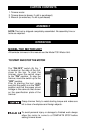
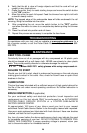
Model 7319 Tilt Base Trimmer is completely
attached at the factory. You can remove
the base from the Model 7301 motor with a
base locking screw (A) Fig. 8.
NOTE: A flat washer (B) Fig. 8 is on the
locking screw.
Model 7319 Tilt Base is designed for use
with 43216PC flush trim bit for trimming into
corners. You may also use it with other “self
pilot” trim bits for conventional trimming at
90° setting.
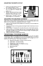
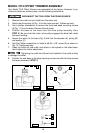
MODEL 7319 TILT BASE TRIMMER ASSEMBLY
Fig. 8
A B
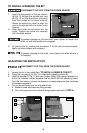
ADJUSTING THE DEPTH OF CUT
DISCONNECT THE TOOL FROM THE POWER SOURCE!
Loosen the base locking screw and move the motor unit up or down to decrease
or increase the depth-of-cut.
You may have to slightly withdraw some bits in the collet to obtain a maximum
depth of cut.
When you withdraw a bit, be certain that at least 1/2" of the
bit shank is engaged in the collet. Do not use bits that result in
having less than 1/2" of the bit shank engaged in the collet. To do so may cause
poor gripping of the collet, resulting in a loose bit. If the bit comes out of the
collet, it could cause damage to the workpiece and/or personal injury.
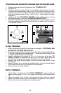
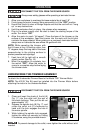
Fig. 9
C
D
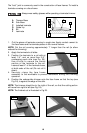
1. Loosen two tilt locking screws (C)
Fig. 9 (one on each side of base)
using the provided wrench.
2. Match the base-aligning index mark
(D) Fig. 9 with the desired angle and
tighten securely.
3. Make a trial cut on scrap material to
check the alignment.
ADJUSTING THE TILT