


10
TO START AND STOP DRILL
1. Make sure drill switch is “OFF”. Make sure power circuit voltage is the
same as that shown on the specification plate of the drill. Connect drill to
power circuit.
2. Squeeze TRIGGER SWITCH (A) Fig. 2, to start motor. As trigger is
squeezed, the drill speed increases. Release trigger to stop motor.
3. A REVERSING SWITCH (B) Fig. 2 – is provided with either model. These
models will operate in either the forward direction (clockwise rotation) for
drilling holes, or the reverse direction (counterclock-wise rotation) for
releasing jammed drill bits. For counterclockwise rotation, stop the motor by
releasing the trigger switch and move the reversing switch to the position
labeled “R”, or in the opposite direction for clockwise rotation.
NOTE: Never attempt to change direction of rotation while switch is
“ON”. To do so, may damage the drill. Be sure switch is “OFF” and
motor has completely stopped before changing direction of rotation.
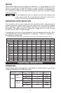
TO INCREASE RPMs
The 7556 is factory assembled with the chuck on drive end marked “LOW” and
will run at the lower RPM shown on the specification plate. To change to the
higher RPM marked on the nameplate proceed as follows:
1. DISCONNECT TOOL FROM POWER SOURCE.
2. Open chuck jaws as wide as possible to gain access to chuck retaining
screw.
3. Place spindle wrench (furnished with drill) on flats of spindle shaft and hold.
With a
3
/16" hex wrench, turn the retaining screw clockwise (left hand threads) and
remove screw from chuck.
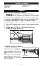
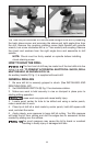
4. While supporting chuck on a solid surface, place wrench on flats of spindle
and allow the opposite end of wrench to rest on the workbench to your left as
shown in Fig. 3. Place chuck pin wrench into chuck key hole so that pin wrench
extends to your left as shown in Fig. 3. Strike the pin wrench a sharp blow with a
hammer to loosen chuck.
5. Turn chuck counterclockwise to unscrew. Remove chuck and two washers
from spindle.
6. Loosen the outer sleeve screw (F) Fig. 2 with a
1
/2” wrench, and remove the
right angle drive (E) Fig. 2, from the sleeve (G) Fig. 2.
7. Place end of right angle drive marked “LOW” into sleeve (G) Fig. 2. Make
sure the flats on the driveshaft engage slot in coupling. Tighten sleeve screw (F)
Fig. 2.
8. Place steel washer and then brass washer (washers removed in Step 5) onto
spindle at end of right angle drive marked “HIGH.”
NOTE: Failure to use these washers may cause chuck to seize on
spindle.
9. Thread chuck onto spindle and seat firmly by reversing procedure in Step 4.
10. Replace and tighten chuck retaining screw securely.
OPERATION