


7
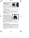
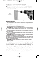
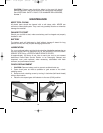
INSTALLING AND REMOVING DRILL
AND SCREWDRIVER BITS
1. CAUTION: Always set reversing button
to center (locked OFF) position when
installing and removing bits.
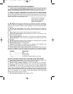
2. The three-jaw chuck is designed for
self-centering of the bit. Open jaws large
enough by turning outer sleeve (A) Fig. 2,
counterclockwise, when viewing the chuck
from the bit end, so that bit shank can be
inserted easily.
3. Clean and insert smooth end of bit as far as it will go into the chuck, or
up to the flutes for small bits.
4. While holding the bit with one hand, turn outer sleeve (A) Fig. 2, clockwise
until the bit is gripped in the chuck.
5. Tighten chuck by holding chuck ring (B) Fig. 2, with one hand while
turning outer sleeve (A) clockwise with other hand. Tighten securely.
WARNING: Do not operate drill motor while installing or removing
bits. Operating drill motor can cause bit to be thrown from chuck
causing personal injury.
6. To remove bit, reverse foregoing procedure.
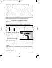
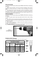
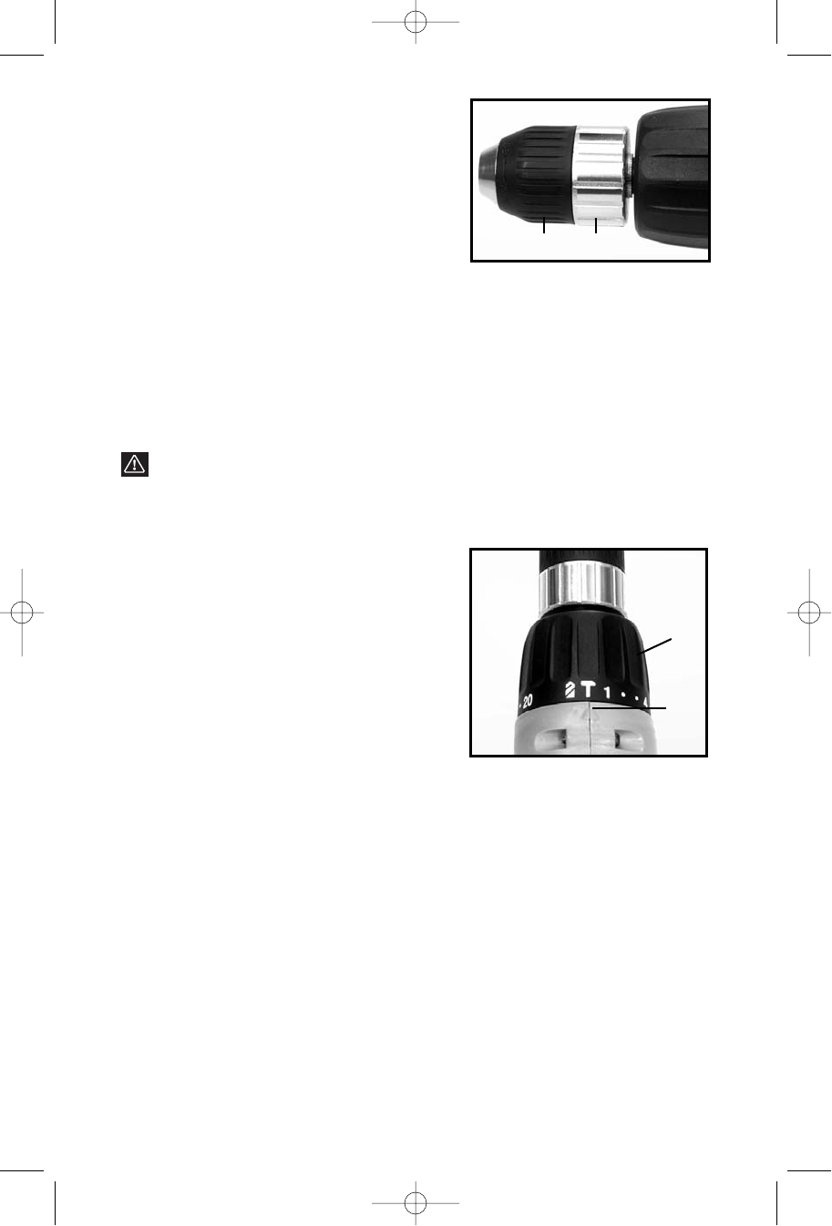
ADJUSTING TORQUE COLLAR
The clutch unit provides twenty clutch
settings, a “Drill” (solid lock-up) setting, and
a hammer (impact) position. Lowest torque is
avaible at setting #1, with maximum torque
available at the “Drill” setting. The amount of
output torque may be adjusted by rotating
the front collar (A) Fig. 3, so that the desired
torque setting is aligned with the index mark
(B) Fig. 3. In general, lower torque settings
are used for driving small screws and other
delicate work, while higher torque settings
are used for driving larger screws. The “Drill” position is used for drilling and for
driving very large screws. The hammer position is used when “impacting” is
needed to assist in the drilling operation such as when drilling in concrete,
bricks, etc.
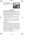
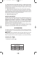
TWO-SPEED GEAR SHIFT
The Models 877 and 887 Cordless Hammer Drill/Drivers have a two-speed
gear shift which provides spindle speed ranges of approximately: 0 to 475
RPM (LOW) and 0 to 1450 RPM (HIGH) for Model 877; 0-500 RPM (LOW) and
0-1500 RPM (HIGH) for Model 887. To change speed ranges: release trigger
switch to stop motor and then slide speed selector (A) Fig. 4, toward rear for
HIGH speed or toward front for LOW speed.
The low speed position is normally used when drilling larger holes and when
driving or removing screws. The high speed position is normally used for
drilling small holes.
Fig. 2
AB
Fig. 3
A
B
900470 - 11-30-00.QXD 9/25/02 11:09 AM Page 7