


11
GENERAL ASSEMBLY INSTRUCTIONS
• Assemble Saw Stand (Fig 1). Set on level surface
and lock both wheels to resist movement while
placing Saw on Stand.
• Fasten Saw Frame Assembly onto assembled
Saw Stand using T-Knobs. (10, Fig 1B)
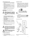
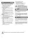
• Install Water Tray Assembly to Frame. (Fig 2)
• Install Motor Support Shaft in Rear Support Post.
(3, Fig 3)
• Install Motor Cutting Head on Motor Support Shaft.
(1, Fig 3)
• Install Blade Guard Assembly onto Cutting Head.
(1, Fig 4) Attach Splash Flap to rear of Guard.
• Place Water Pump Assembly in Water Tray and
connect Tubing from Blade Guard. Plug cord into
Water Pump Outlet on the side of Power Switch
Housing.
• Install the 10” continuous rim Diamond Blade. (6,
Fig 4)
• Install Cart Extension and Accessories as needed.
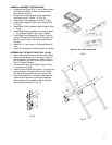
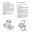
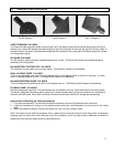
ASSEMBLING THE SAW STAND (FIGS. 1A & B)
• Open carton and remove all the Saw Stand Parts.
• Attach the two Wheels (3) to the Inner Frame (2)
with the M6x45 Cap Screws (4). Retain with the
M6 Flatwashers (5) and Locknuts (6) as shown in
Fig 1A. Tighten Securely.
• Set the Inner Frame (2) inside the Outer Frame
(1) as shown in Fig 1B.
• Install the two M10x56 Cap Screws (7) through the
pivoting holes in the legs of each frame. Retain
with the M10 Flatwashers (8) and Locknuts (9).
• After the Saw Stand is completely assembled as
shown and all fasteners are securely tightened,
the tile saw can be installed on Stand using the
two Saw Stand Knobs (10, Fig 1B).
Fig 1A
WATER TRAY INSTALLATION
FIG 2
Fig 1B