


ALWAYS USE SAFETY GLASSES. Everyday eyeglasses are NOT safety
glasses. Also use face or dust mask if operation is dusty. ALWAYS WEAR CERTIFIED SAFETY
EQUIPMENT:
• ANSIZ87.1eyeprotection(CAN/CSAZ94.3),
• ANSIS12.6(S3.19)hearingprotection,
• NIOSH/OSHArespiratoryprotection.
Important
SafetyInstructions.
ASSEMBLY
Lock off trigger, disconnect air line from tool and remove fasteners from
TRIGGER
Keep fingers AWAY from trigger when not driving fasteners to avoid accidental
firing. Never carry tool with finger on trigger. In bump action mode (contact actuation mode) tool
will fire a fastener if safety is bumped while trigger is depressed.
In accordance with the ANSI Standard SNT-101-2002, the PORTER-CABLE nailers are assem-
bled with a sequential action trigger. The NS150B is equipped with a selectable trigger
allowing one trigger to choose single sequential action trigger mode or bump action trigger
mode. However, a bump action trigger kit may be purchased for the NS100B. For a replace-
ment trigger or to order a bump action trigger contact your authorized service center or call
1-888-848-5175.
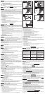
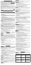
Trigger Removal (Fig. 2)
1. Lock off trigger.
2. Remove air from the tool.
3. Remove rubber grommet (N) from end of dowel pin (M).
4. Remove dowel pin.
5. Remove trigger assembly from trigger cavity under the handle of the tool housing.
Trigger Installation
1. Insert the trigger kit into trigger cavity.
2. Ensure that trigger spring (O) is placed around the trigger valve stem.
3. Align the holes of the trigger with the housing holes, then insert the dowel pin (M) through
the entire assembly.
4. Push the rubber grommet (N) onto the end of the dowel rod.
OPERATION
PREPARING THE TOOL
Read the section titled for Pneumatic Tools
at the beginning of this manual. Always wear proper eye [ANSI Z87.1 (CAN/CSA Z94.3)] and
hearing protection [ANSI S12.6 (S3.19)] when operating this tool. Keep the stapler pointed away
from yourself and others. For safe operation, complete the following procedures and checks
before each use of the stapler.
These nailers are designed to be used without oil.
1. Before you use the nailer, be sure that the compressor tanks have been properly drained.
2. Wear proper eye, hearing and respiratory protection.
3. Lock the magazine release in the back position and remove all fasteners from the
magazine.
4. Check for smooth and proper operation of contact trip and pusher assemblies. Do not use
tool if either assembly is not functioning properly. NEVER use a tool that has the contact
trip restrained in the up position.
5. Check air supply. Ensure that air pressure does not exceed recommended operating limits;
70 to 120 psi, (4.9 to 8.3 bar, 5 to 8.5 kg/cm
2
).
6. Connect air hose.
7. Check for audible leaks around valves and gaskets. Never use a tool that leaks or has
damaged parts.
To reduce the risk of injury. wear proper eye [ANSI Z87.1 (CAN/CSA
Z94.3)] and hearing protection [ANSI S12.6 (S3.19)] when operating this tool.
Do not keep trigger depressed when tool is not in use. Keep the lock-off switch
rotated to the right (OFF) when the tool is not in use. Serious personal injury may result.
Lock off trigger, disconnect air line from tool and remove fasteners from
The NS100B stapler is equipped with a trigger lock-off switch (J) which when rotated to the
right, prevents the tool from actuating. When the switch is in the unlocked position, the tool
will be fully operational. The trigger should always be locked off whenever any adjustments are
made or when tool is not in use.
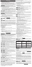
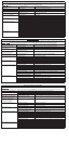
LOADING THE TOOL (FIG. 3)
Keep the tool pointed away from yourself and others. Serious personal injury
may result.
Never load fasteners with the contact trip or trigger activated. Personal injury
may result.
Disconnect tool from air supply before removing or re-installing no-mar pad.
1. Read all before using tool.
2. Connect to air supply.
3. Lock off trigger. (NS100B only)
4. Push the magazine release (F) then slide magazine (E) to open chamber.
5. Position stapler on a stable surface so contact trip is pointing upward and away from
you.
6. Insert fasteners into the top chamber of the magazine.
7. Slide magazine until it clicks, securing the magazine.
To reduce the risk of injury, wear proper eye [ANSI Z87.1 (CAN/CSA
Z94.3)] and hearing protection [ANSI S12.6 (S3.19)] when operating this tool.
The NS150B can be actuated using one of two modes: single sequential action trigger mode
and bump action trigger mode.
The NS100B can be actuated using the single sequential action trigger mode.
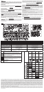
Sequential action trigger - (Fig. 1, 5)
A fastener will fire each time the trigger is depressed as long as the contact trip
remains depressed which could result in inadvertant actuation.
The sequential action trigger’s intended use is for intermittent fastening where very careful
and accurate placement is desired. The NS100B is ready to use in the sequential action trig-
ger mode. On the NS150B, push selectable trigger button (A) from back of trigger and turn
indicator to the position. The tool is now ready to operate in the single sequential action
trigger mode
1. Depress the contact trip firmly against the work surface.
2. Depress the trigger.
Bump action trigger -
(Fig. 1, 5)
The bump action trigger’s intended use is for rapid fastening on flat, stationary surfaces.
Using the bump action trigger, two methods are available: place actuation and bump
actuation. On the NS150B, push selectable trigger button (A) from back of trigger and turn
indicator to the
position. The tool is now ready to operate in the single sequential action
trigger mode
To operate the tool using the
1. Depress the contact trip against the work surface.
2. Depress the trigger.
To operate the tool using the
1. Depress the trigger.
2. Push the contact trip against the work surface. As long as the trigger is depressed, the tool
will fire a fastener every time the contact trip is depressed. This allows the user to drive
multiple fasteners in sequence.
Do not keep trigger depressed when tool is not in use. Keep the lock-off switch
rotated to the right (OFF) when the tool is not in use.
-
• LockOFFtrigger(NS100Bonly).
• Disconnectairsupply.
• Avoidcontactwithtriggerduringadjustments.
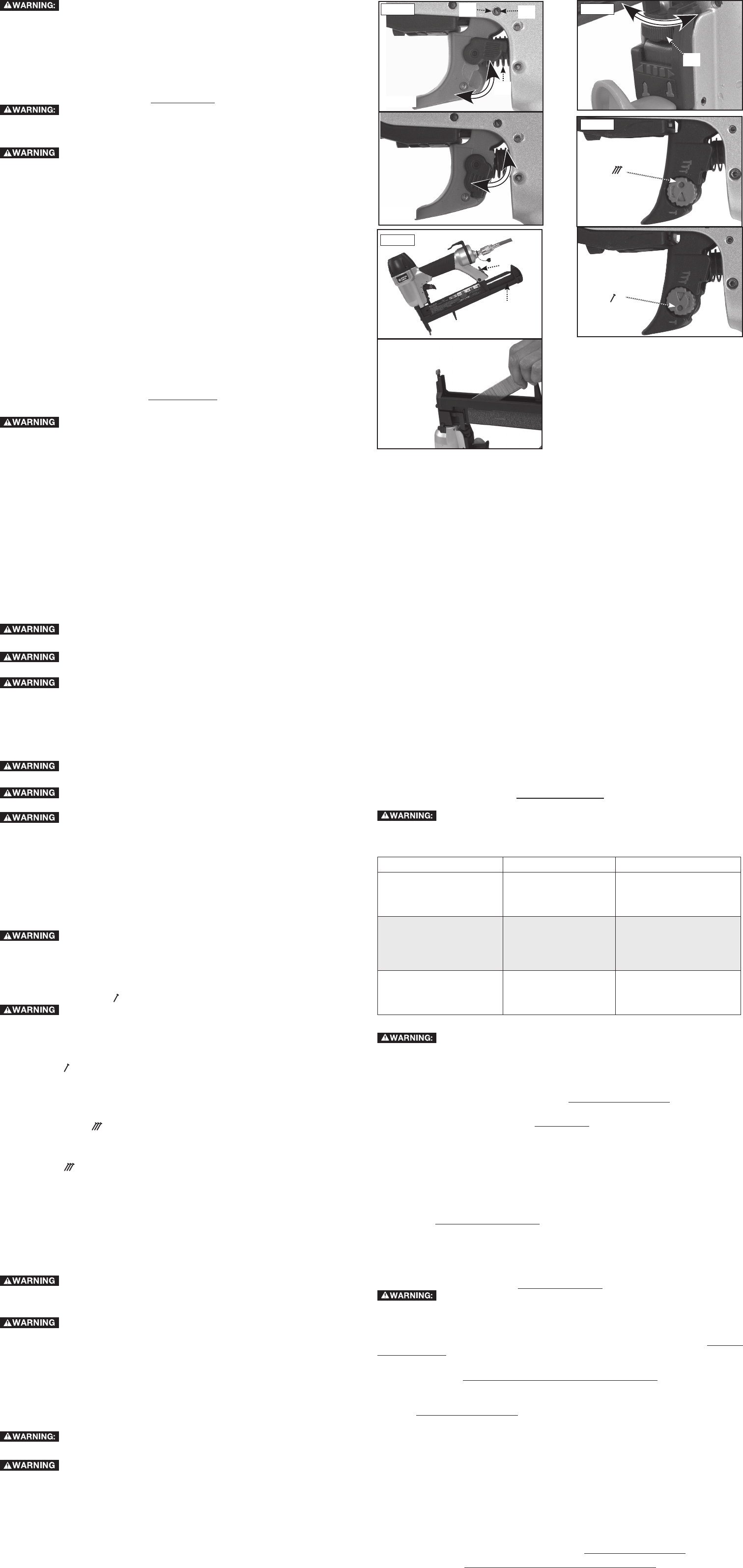
The depth that the fastener is driven can be adjusted using the depth adjustment next to the
trigger of the tool.
1. To drive the fastener shallower, rotate the depth setting wheel (L) to the right.
2. To drive a fastener deeper, rotate the depth setting wheel (L) to the left.
CLEARING A JAMMED FASTENER
Lock off trigger, disconnect air line from tool and remove fasteners from
Keep the tool pointed away from yourself and others. Serious personal injury
may result.
1. Lock off trigger (NS100B only).
2. Disconnect air supply from tool.
3. Push the magazine release then slide magazine to open chamber.
4. Position stapler on a stable surface so contact trip is pointing upward and away from
you.
5. Remove ALL fasteners in the top chamber of the magazine.
6. Remove bent fastener, using pliers if necessary.
7. If driver blade is in the down position, insert screwdriver or other rod into nosepiece and
push driver blade back in position.
8. Reinsert fasteners into the top chamber of the magazine (see Loading the Tool).
9. Slide magazine until it clicks, securing the magazine.
10. Reattach air supply.
Should fasteners continue to jam frequently in nosepiece, have tool serviced by an
authorized PORTER-CABLE service center.
When operating tools at temperatures below freezing:
1. Make sure compressor tanks have been properly drained prior to use.
2. Keep tool as warm as possible prior to use.
3. Make certain all fasteners have been removed from magazine.
4. Lower air pressure to 80 psi or less.
5. Reconnect air and and load nails into magazine.
6. Actuate the tool 5 or 6 times into scrap lumber to lubricate o-rings.
7. Turn pressure up to operating level (not to exceed 120 psi) and use tool as normal.
8. Always drain the compressor tanks at least once a daily.
Tool should operate normally. However, keep tool out of direct sunlight as excessive heat can
deteriorate bumpers, o-rings and other rubber parts resulting in increased maintenance.
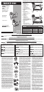
BELT HOOK (FIG. 1)
The PORTER-CABLE nailers include an integrated belt hook (I) and can be rotated to either
side of the tool to accommodate left or right handed users. It can also be rotated out of the
way when not in use.
If the hook is not desired at all, it can be removed from the tool.
1. Lock off trigger.
2. Disconnect the tool from air supply.
3. Using the appropriate hex wrench, remove the end cap screws from the end cap of the
tool.
4. Remove the belt hook.
5. Replace end cap and gasket. Ensure that the three screws are tight.
6. Replace and tighten air fitting.
MAINTENANCE
Lock off trigger, disconnect air line from tool and remove fasteners from
DAILY MAINTENANCE CHART
ACTION
Drain compressor tanks
and hoses daily.
Prevents accumulation
of moisture in com-
pressor and nailer.
Open petcocks or other
drain valves on compressor
tanks. Allow any accumulated
water to drain from hoses.
Clean magazine, magazine
release and contact
trip mechanism.
Permits smooth opera-
tion of magazine, reduces
wear and prevents jams.
Blow clean with compressor
air. The use of oils, lubricants
periodically or solvents is
not recommended as they
tend to attract debris.
Before each use, check
to insure all screws,
nuts and fasteners are
tight and undamaged.
Prevents jams, leaks
and premature fail-
ure of tool parts.
Tighten loose screws
or other fasteners using
the appropriate hex
wrench or screwdriver.
CLEANING
Never use solvents or other harsh chemicals for cleaning the non-metallic
parts of the tool. These chemicals may weaken the materials used in these parts. Use a cloth
dampened only with water and mild soap. Never let any liquid get inside the tool; never immerse
any part of the tool into a liquid.
REPAIRS
For assistance with your tool, visit our website at www.deltaportercable.com for a list of service
centers, or call the PORTER-CABLE Customer Care Center at (888) 848-5175.
SERVICE
REPLACEMENT PARTS
Use only identical replacement parts. For a parts list or to order parts, visit our website at ser-
vicenet.porter-cable.com. You can also order parts from your nearest PORTER-CABLE Factory
Service Center or PORTER-CABLE Authorized Warranty Service Center. Or, you can call our
Customer Care Center at (888) 848-5175.
SERVICE AND REPAIRS
All quality tools will eventually require servicing and/or replacement of parts. For information
about PORTER-CABLE, its factory service centers or authorized warranty service centers, visit
our website at www.deltaportercable.com or call our Customer Care Center at (888) 848-5175.
All repairs made by our service centers are fully guaranteed against defective material and
workmanship. We cannot guarantee repairs made or attempted by others.
You can also write to us for information at PORTER-CABLE, 4825 Highway 45 North, Jackson,
Tennessee 38305 - Attention: Product Service. Be sure to include all of the information shown
on the nameplate of your tool (model number, type, serial number, etc.).
ACCESSORIES
Since accessories other than those offered by Porter-Cable have not been
tested with this product, use of such accessories could be hazardous. For safest operation,
only Porter-Cable recommended accessories should be used with this product.
A complete line of accessories is available from your PORTER-CABLE Factory Service Center
or a PORTER-CABLE Authorized Warranty Service Center. Please visit our Web Site www.del-
taportercable.com for a catalog or for the name of your nearest supplier.
PORTER-CABLE will repair, without charge, any defects due to faulty materials or workman-
ship for three years from the date of purchase. This warranty does not cover part failure due to
normal wear or tool abuse. For further detail of warranty coverage and warranty repair informa-
tion, visit www.deltaportercable.com or call (888) 848-5175. This warranty does not apply to
accessories or damage caused where repairs have been made or attempted by others. This
warranty gives you specific legal rights and you may have other rights which vary in certain
states or provinces.
In addition to the warranty, PORTER-CABLE tools are covered by our:
PORTER-CABLE will maintain the tool and replace worn parts
caused by normal use, for free, any time during the first year after purchase.
If you are not completely satisfied with the performance
of your PORTER-CABLE Power Tool, Laser, or Nailer for any reason, you can return it within 90
days from the date of purchase with a receipt for a full refund – no questions asked.
This warranty does not apply to products sold in Latin America. For products
sold in Latin America, see country specific warranty information contained in the packaging, call
the local company or see website for warranty information.
To register your tool for warranty service visit our website at
www.deltaportercable.com
.
If your warning labels (Fig. 6) become illegible or are missing, call (888) 848-5175 for a free
replacement.
Fig. 3
Fig. 5
F
E
A
NS150B
NS150B
A
Fig. 2
NS100B
NS100B
M
N
O
L