


6
UNPACKING AND CLEANING
Carefully unpack the machine and all loose items from the
shipping container(s). Remove the rust-preventative oil from
unpainted surfaces using a soft cloth moistened with mineral
spirits, paint thinner or denatured alcohol.
NOTICE
AVIS
AVISO
fr
sp
Do not use highly volatile solvents such as
gasoline, naphtha, acetone or lacquer thinner for cleaning your
machine.
After cleaning, cover the unpainted surfaces with a good quality
household floor paste wax.
ASSEMBLY
To reduce the risk of injury, turn unit "OFF"
and disconnect it from power source before installing and
removing accessories, before adjusting or when making
repairs. An accidental start-up can cause injury.
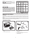
ASSEMBLY TOOLS REQUIRED
•5 mm hex wrench (included)
ASSEMBLY TIME ESTIMATE
Assembly for this machine takes approximately 30 minutes.
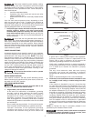
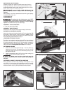
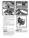
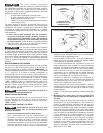
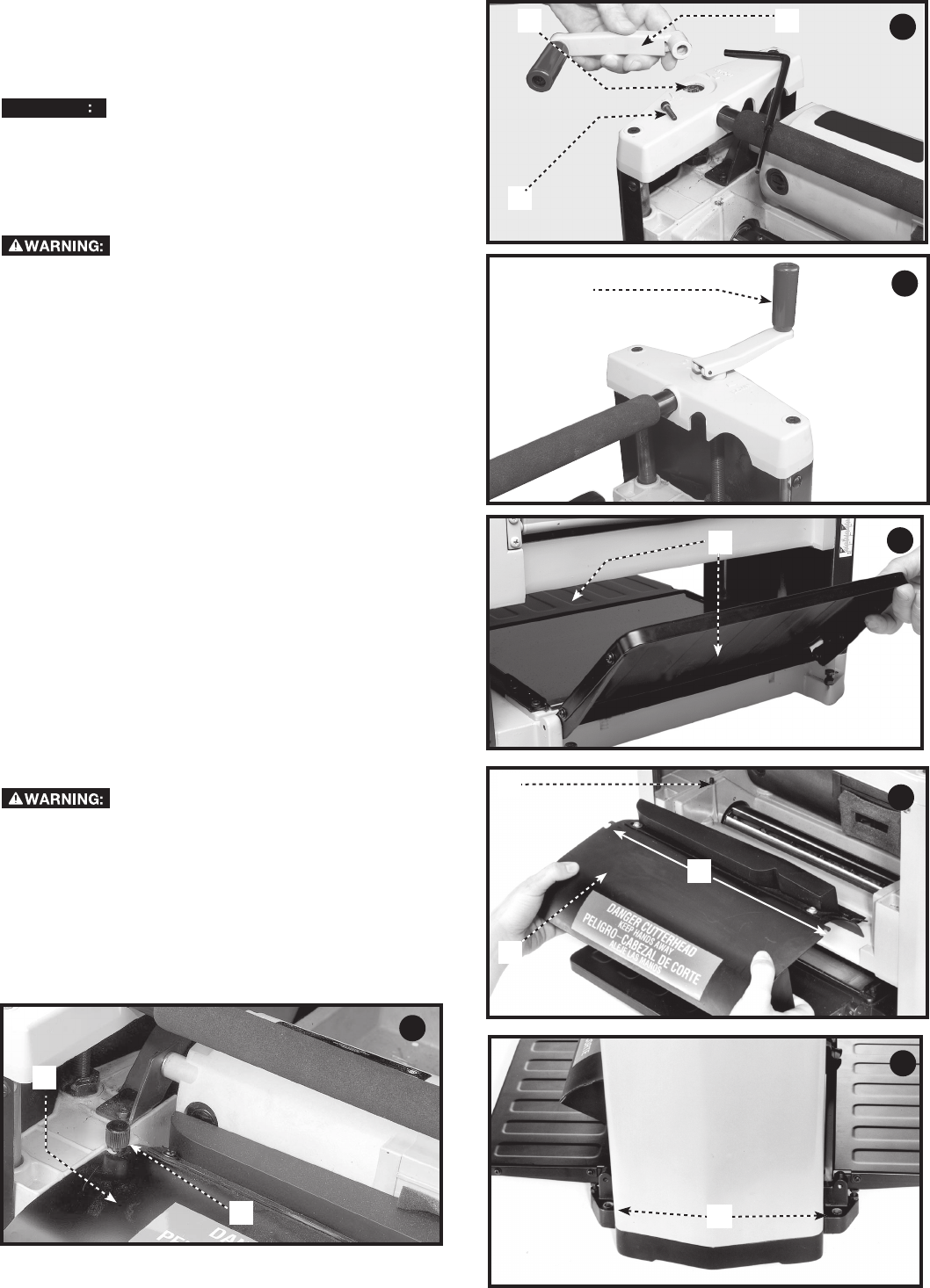
RAISING AND LOWERING HANDLE
Attach the raising and lowering handle (A) Fig. 4 to the shaft (B)
and fasten in place with M5 x 20 mm screw (C). NOTE: Ensure
that the flats of the handle and the flats on the shaft are aligned.
Flip handle (A) upward as shown in Fig. 5.
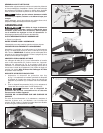
LOWERING EXTENSION TABLES
The infeed and outfeed extension tables (A) Fig. 6 are shipped
attached to the machine in the raised position. Lower the tables
(A) on both sides of the planer (Fig. 6). The top surface of extension
tables should be level with the planer table. To check and adjust,
refer to the section Leveling Extension Tables in this manual.
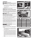
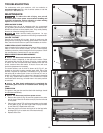
CUTTERHEAD GUARD
1. Attach the cutterhead guard (A) Fig. 7 to the planer by
inserting the end of the guard over the top of the
cutterhead. Place the slots in the cutterhead guard (C) over
the tapped holes (B).
2. Fasten cutterhead guard (A) Fig. 8 to planer using two
knobs, one of which is shown at (D) Fig. 8.
Make sure that the cutterhead guard is
properly secured with the knobs before operating this
machine.
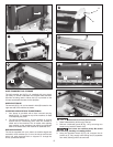
FASTENING PLANER TO SUPPORTING SURFACE
During operation, if there is any tendency for the planer to tip
over, slide or "walk" across the supporting surface, the planer
must be secured to the supporting surface. Four holes (two of
which are shown at (A) Fig. 9 are provided for this purpose.
5
6
A
A
C
A
B
4
D
A
A
B
C
A
8
9
7