


7
12A
10
OPERATION
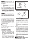
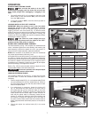
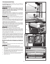
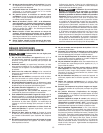
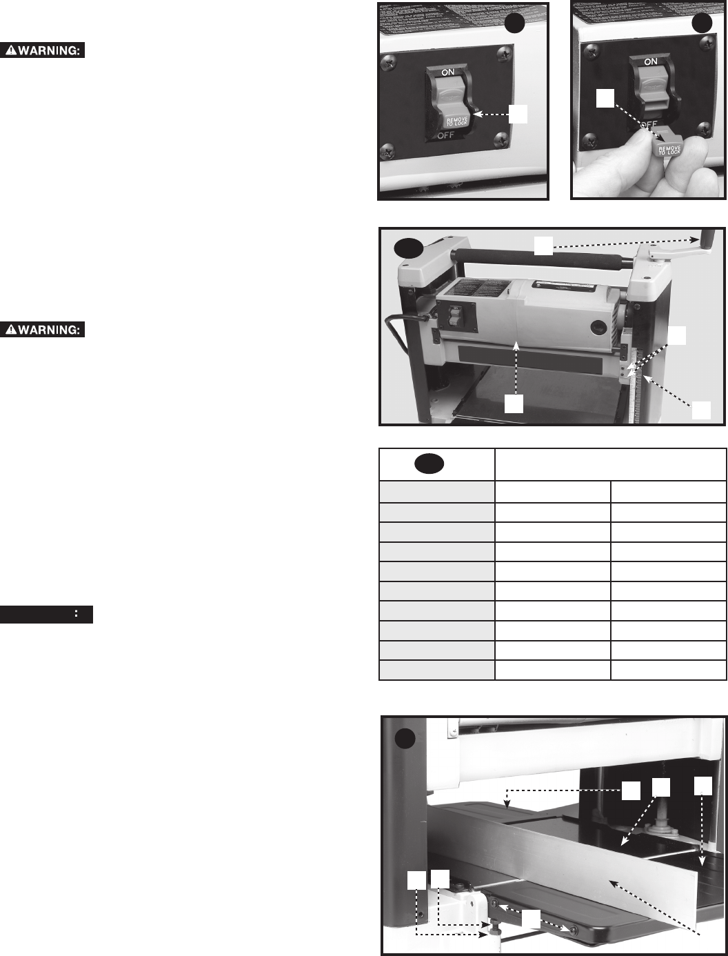
STARTING AND STOPPING PLANER
Make sure that the switch is in the "OFF"
position before plugging cord into outlet. Do not touch the
plug’s metal prongs when unplugging or plugging in the
cord.
1. The on/off switch (A) Fig. 10 is located on the front of the
planer moter. To turn the machine "ON", move the switch
up to the "ON" position.
2. To turn the machine "OFF", move the switch (A) down to
the "OFF" position.
LOCKING SWITCH IN THE "OFF" POSITION
IMPORTANT: When the machine is not in use, the switch
should be locked in the "OFF" position to prevent
unauthorized use. To lock the machine, grasp the switch
toggle (T) and pull it out of the switch (Fig. 11). With the switch
toggle (T) removed, the switch will not operate. However, should
the switch toggle be removed while the planer is running, the
machine can be turned "OFF," but cannot be restarted without
reinserting the switch toggle (T).
In the event of a power outage (such as a
breaker or fuse trip), always move the switch to the "OFF"
position until the main power is restored.
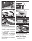
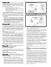
RAISING AND LOWERING HEAD ASSEMBLY
The head assembly (A) Fig. 12A contains the cutterhead feed
rollers, cutterhead guard and motor. Raising and lowering the
head assembly controls the depth-of-cut on your planer. To
raise or lower the head assembly, rotate the handle (D).
NOTE: One revolution of the handle will move the cutterhead
up or down approximately 5/64 inch (2 mm).
An English/metric scale and pointer (C) is located on the front of
the planer to indicate the height of the cutterhead. Adjustment
to the pointer can be made by running a piece of wood through
the machine. Measure the thickness of the workpiece and if
an adjustment is necessary, loosen two screws (B) and adjust
pointer accordingly. Then tighten two screws.
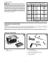
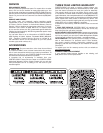
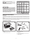
Refer to Fig. 12B for recommended maximum depth-of-cut for
various board widths of soft and hard woods.
NOTICE
AVIS
AVISO
fr
sp
Continuous operation at the deepest depth
of cut can cause premature motor failure.
A
A
C
D
B
12B
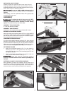
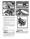
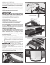
LEVELING EXTENSION TABLES
The extension tables (A) and (G) Fig. 14 must be level with
the planer table. To check the extension tables and adjust if
necessary:
1. Place a straight edge (B) Fig. 14 on the planer table (E) with
one end extending out over the infeed table (A). Check to
see if the infeed table is level with the planer table on both
ends of the planer table.
2. If an adjustment is necessary, loosen the locknut (C)
Fig. 14, and adjust the stop screw (D) on each side of
the infeed table (A) until the extension table is level with
the planer table (E). Tighten the locknut (C). Recheck and
make certain that the inside edge of table extension is
level with the planer table. If necessary, loosen the two
screws (F), adjust the extension table and retighten the
two screws (F). Adjust the opposite side of the table in
the same manner. Make certain that the extension table is
solidly supported when downward pressure on the table is
applied.
3. Check and adjust the outfeed table (G) in the same
manner.
A
B
D
C
E
G
F
14
11
T
Maximum depth-of-cut
Board Width Soft Woods Hard Woods
2 inches (50.8 mm) 3/32 inches (2.4 mm) 3/32 inches (2.4 mm)
4 inches (101.6 mm) 3/32 inches (2.4 mm) 3/32 inches (2.4 mm)
6 inches (152.4 mm) 3/32 inches (2.4 mm) 3/32 inches (2.4 mm)
7 inches (177.8 mm) 3/32 inches (2.4 mm) 3/32 inches (2.4 mm)
8 inches (203.2 mm) 3/32 inches (2.4 mm) 3/32 inches (2.4 mm)
9 inches (228.6 mm) 5/64 inches (2 mm) 1/16 inches (1.6 mm)
10 inches (254 mm) 1/16 inches (1.6 mm) 3/64 inches (1.2 mm)
11 inches (279.4 mm) 1/16 inches (1.6 mm) 3/64 inches (1.2 mm)
12 inches (304.8 mm) 1/16 inches (1.6 mm) 3/64 inches (1.2 mm)