


14
Work Table Parallel to Cutterhead
The work table is set parallel to the cutterhead at
the factory and no further adjustment should be
necessary. If your machine is planing a taper,
first check to see if the knives are set properly in
the cutterhead. Then check to see if the work
table is set parallel to the cutterhead. Proceed
as follows:
1. Disconnect machine from power source.
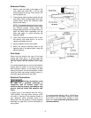
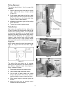
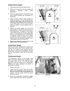
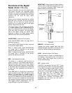
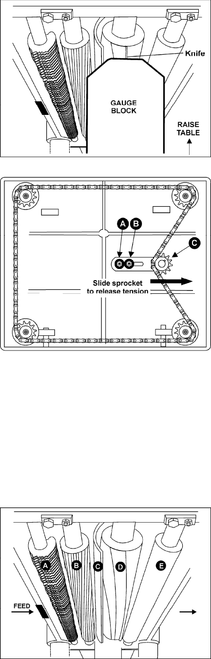
2. Place the gauge block (Figure 21) on the
work table directly under the edge of a knife
as shown. Make slight contact by gently
raising table.
3. Move the gauge block to the opposite end of
the work table. NOTE: Distance from the
work table to edge of knife should be the
same.
4. If the work table is not parallel to the
cutterhead, perform the adjustment
procedure as follows.
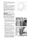
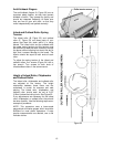
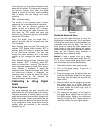
5. Remove bolts holding the planer to the
stand. Carefully tilt planer on its side to
expose underside of base (Figure 22).
6. Remove bolt (A, Figure 22) and loosen bolt
(B, Figure 22) which will allow you to move
the idler sprocket assembly (C, Figure 22)
far enough to release tension on the chain.
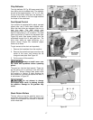
7. Remove the chain from the particular
sprocket on the corner of the base that you
need to adjust.
8. Turn the sprocket by hand to bring that
corner into adjustment with the other three
corners. NOTE: Turning sprocket clockwise
will increase the distance between the
working table and the head casting;
counterclockwise will decrease the distance.
This adjustment is very sensitive and it
should not be necessary to turn the sprocket
more than one or two teeth.
9. When adjustments are correct, replace
chain around corner sprocket, slide idler
sprocket (C, Figure 22) back to re-tension
chain, tighten bolt (B, Figure 22) and insert
and tighten bolt (A, Figure 22).
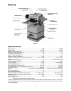
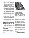
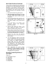
Know the Transmitting Rollers of
Your Planer
(Figure 23)
A. Anti-Kickback Fingers
B. Infeed Roller
C. Chipbreaker
D. Cutterhead
E. Outfeed Roller
Figure 21
Figure 22
Figure 23