


13
Riving Knife and Guard Installation
Description
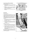
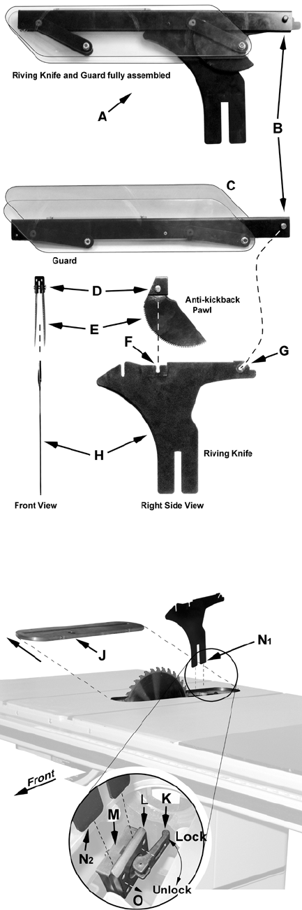
Referring to Figure 9:
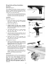
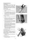
The complete riving knife and guard assembly is
shown in A. Before installing onto the saw, the anti-
kickback pawl (E) must be separated from the
riving knife (H) as described below.
1. Press and hold the quick-release button (D) on
the base of the anti-kickback pawl (E) and lift
the pawl to remove from the riving knife (H).
Installation
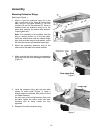
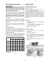
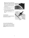
Referring to Figure 10:
1. Set the saw blade to the 90 degree position
and raise it all the way (refer to Handwheel
Adjustments on page 14).
2. Remove the table insert (J).
3. Located inside the table and accessible
through the insert opening (Figure 10 inset),
place the quick-release clamp lock handle (K)
in the unlock position.
4. The floating clamp block (L) is spring loaded
and will move away (O) from the fixed
block (M), leaving a gap.
5. Insert the bottom of the riving knife (N
1
, N
2
) all
the way into the gap between the clamp blocks
(L, M), then lock the handle (K).
6. Replace the insert (J) back on the table. The
saw blade and riving knife should protrude
through the slot in the insert.
Referring back to Figure 9:
7. Attach the anti-kickback pawl (E) by pressing
and holding the quick-release button (D) and
inserting the lock pin of the pawl into the
appropriate slot (F) on the riving knife.
8. In similar manner attach the guard (C) by
pressing and holding the quick-release button
(B) and inserting the lock pin of the guard into
the appropriate slot (G) on the riving knife.
You should feel a snap as each piece locks in
position. Attempt to lift as a test to make sure
that they are securely locked in place.
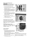
Adjustment
The clamping blocks (L, M, Fig. 10) are adjusted at
the factory and no further adjustment of the blade
guard and riving knife assembly should be
necessary. However, proper alignment is very
important. Before operating the table saw, read
the Riving Knife Adjustment section (page 18) to
verify and follow the adjustment procedure if
necessary.
Figure 9
Figure 10