


15
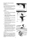
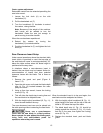
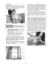
Castor system adjustment
Retractable castors can be extended permitting the
saw to be moved:
1. Loosen the lock knob (A) on the side
handwheel (C).
2. Pull the handwheel out (F).
3. Turn the handwheel (C) clockwise to extend
the castors, raising the saw.
Note: Because of the weight of the machine,
both hands will be needed to turn the
handwheel. Raise the saw just enough to
permit moving to another location.
When the saw has been repositioned:
4. Retract the castors by turning the
handwheel (C) counterclockwise.
5. Push the handwheel in (F) and tighten the lock
knob (A).
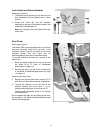
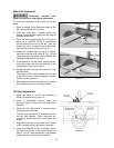
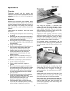
Zero-Clearance Insert Setup
Under normal operations where the standard table
insert (which is provided) is used, the top edge of
the saw blade will come to rest approximately 1/8"
below the table surface when the blade height is
positioned all the way down.
In situations where a zero-clearance insert is
desired, the saw blade may be lowered further for
accommodation of inserts that have potential
clearance issues with the blade. This is done as
follows:
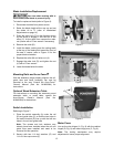
1. Remove the guard and pawl (Figure 9,
Items C, E).
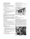
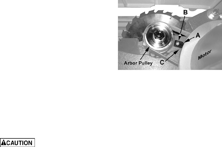
2. Open the side cover and locate the blade depth
stop (A, Fig. 12) located between the arbor
pulley and motor.
3. Using a 6mm hex wrench, loosen the locking
screw (B, Fig. 12).
4. This will allow the depth stop to swing free and
the saw blade to be adjusted lower.
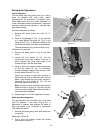
5. With the height adjust handwheel (B, Fig. 11),
lower the saw blade all the way.
The zero-clearance insert can now be placed into
the table opening without contacting the saw blade.
Never use a zero-clearance
insert with the saw blade in a tilted position.
Never operate the saw without the blade guard,
riving knife and anti-kickback pawls for
operations where they can be used.
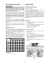
Figure 12
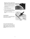
When the standard insert is to be used again, the
saw blade must be readjusted as follows:
6. With the height adjust handwheel (B, Fig. 11),
adjust height of the saw until the top of the saw
blade is 1/8" below the top of the table.
7. The blade depth stop (A, Fig. 12) should be
resting against the trunnion (C, Fig. 12). Verify
that this is the case; then tighten the locking
screw (B, Fig. 12).
8. Replace the standard insert, pawl and blade
guard.