


12
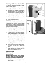
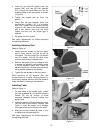
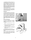
2. Insert the two M10x25 socket head cap
screws (AA), with two M10 flat washers
(EE), through the fence base and into the
threaded holes on the pivot plate, as shown
in Figure 9.
3. Tighten the screws with an 8mm hex
wrench.
4. Check that the gap between fence and
sanding belt is about 1/16”. If it is greater
than 1/16”, loosen (do not remove) the four
screws on the sides of the fence assembly
with a hex wrench, and push the fence
toward the belt until the proper gap is
attained.
5. Re-tighten the four screws.
See under “Adjustments” for further instruction
on adjusting the fence.
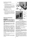
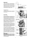
Installing Abrasive Disc
Refer to Figure 10:
1. Loosen the two screws on the front panel
with a 10mm wrench, and pull out on the
front panel. The front panel will not remove
from the sander, but this will allow more
room for positioning the abrasive disc.
2. Remove the backing from the abrasive disc
to expose the adhesive, and carefully center
it on the sander’s metal disc. Press the
abrasive disc firmly, working from the center
out to prevent creases or air bubbles.
3. Tighten the two screws on the front panel.
When removing an old abrasive disc, use
mineral spirits or a similar cleaning product to
remove any residual adhesive from the sander’s
metal disc before installing a new abrasive.
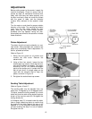
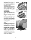
Installing Table
Refer to Figure 11:
1. On both sides of the sander body, loosen
the locking wheels (A), and pull the trunnion
holders (B) out far enough to allow
clearance between trunnion holders and
sander body.
2. Install the table by sliding the table trunnions
into the slots of the trunnion holders. See
Figure 11 inset. Be careful not to damage
the angle pointer on the left trunnion holder.
3. Slide the trunnion holders (B) back in, and
re-tighten the locking wheels (A).
See under “Adjustments” for further instruction
on adjusting the table.
Figure 9
Figure 10
Figure 11