


16
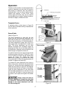
A zero-degree stop screw (D, Figure 17) is
located behind the disc. The block should be set
for quick placement of the table to the zero
position (90 degree table). The block must be
swung out of position for the table to be tilted
downward. If major adjustment of the zero-
degree stop is necessary, loosen the socket
head cap screws (E) and raise or lower the
bracket. For fine adjustment, loosen the hex nut
(F) and turn the stop screw (D) in or out as
needed. Re-tighten hex nut (F).
Periodically check zero position on the table by
using a combination square. The angle between
the table and disk should be 90 degrees when
the trunnion pointer is at zero.
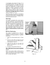
Work Stop
Your sander is equipped with a work stop for
use with the belt arm in the horizontal position
(see Figure 25). When installed, the work stop
will prevent a work piece from being thrown from
the belt. If removed for through-sanding, the
work stop should be immediately reinstalled
after the through-sanding operation (unless the
fence attachment is used in its place for 45-
degree or vertical positions of the arm). Use a
10mm hex wrench to remove or install the work
stop.
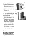
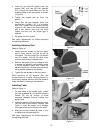
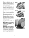
Belt Arm Positioning
Your sander is equipped with an index pin
arrangement to lock the belt arm in 0-degree,
45-degree, and 90-degree positions. To position
the belt arm:
1. Loosen the locking handle shown in Figure
18.
2. Pull out on the index pin (Figure 19), and
swing the belt arm into the desired position.
Then release the index pin.
3. Check that the index pin has gone into
position by attempting to move belt arm
back and forth.
4. Re-tighten locking handle (Figure 18).
When positioning the arm at any non-standard
angle, make sure the locking handle is tightened
securely.
NOTE: If the locking handle conflicts with the
motion of the belt arm, pull up on the handle and
rotate it out of the way, then release it, making
sure it re-seats itself properly.
Figure 18
Figure 19