


9
Assembly
Exposed metal surfaces, such as the table and
fence, have been given a protective coating at
the factory. This coating should be removed with
a soft cloth and solvent (such as mineral spirits)
once the machine has been assembled. Do not
use an abrasive pad as it may scratch the
exposed surfaces.
NOTE: If any procedure described herein needs
further clarification, consult the assembly
drawings at the back of this manual.
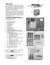
Tools required for assembly:
3mm, 4mm and 6mm hex (Allen) wrenches
17mm, 14mm, (two)12mm open-end wrenches
screwdriver
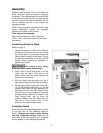
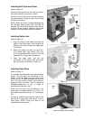
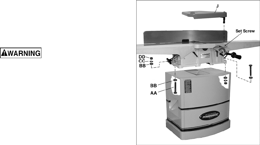
Assembling Jointer to Stand
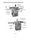
Refer to Figure 6.
1. Locate the stand on a level floor. If desired,
the stand can be secured to the floor using
two anchor bolts (not provided) through the
holes inside the bottom of the stand. If using
an optional mobile base, be sure to lock the
wheels before assembling, operating or
adjusting the jointer.
The jointer is very heavy.
Exercise proper caution when lifting it.
2. Use a hoist or forklift with straps, to lift the
jointer onto the stand. (The front of the
jointer should face the same direction as
curved front of the stand.)
3. Shift the jointer atop the stand until the 3-
hole pattern aligns in jointer base and stand.
4. Secure jointer base to stand with three 3/8”-
16 x 2-3/8” carriage bolts (AA), six 3/8” flat
washers (BB), three 3/8” lock washers (CC)
and three 3/8” hex nuts (DD). (Note: On the
left hand hole, it may be easier to insert the
carriage bolt from beneath as shown.) Only
finger tighten bolts until all three are
properly inserted; then fully tighten the hex
nuts with a 14mm wrench and a 17mm
wrench on the heads of the screws.
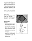
Cutterhead Guard
Place the post of the cutterhead guard (J, Figure
6) into the hole on the rabbeting ledge as
shown. (Always use caution when working
near the cutterhead knives!) Rotate the set
screw with a 4mm hex wrench until it tightens
into the groove on the cutterhead guard post.
Figure 6