


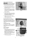
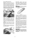
18
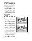
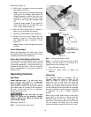
Referrin
g
to Fi
g
ure 18:
2. With a 5mm hex wrench, loosen two socket
head button screws (E).
Note: These screws are accessible through
openings on the floating clamp block (B)
located diagonally on either side of the lock
handle (A). They secure the fixed clamp
block (C) to the riving knife extension plate
(F).
Loosening these screws (E) will allow the
fixed clamp block (C) to slide back and
forth on the extension plate (F).
3. Slide the fixed clamp block (F) toward or
away from the saw blade as required.
4. Tighten the socket head button screws (E).
5. Reinsert the riving knife; tighten the lock
handle (A, Figure 17) and check that the
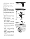
saw blade/knife gap is between 3 - 8mm
(Figure 19).
Note: Attempt to make the gaps as even as
possible.
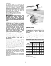
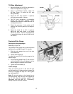
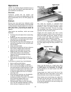
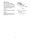
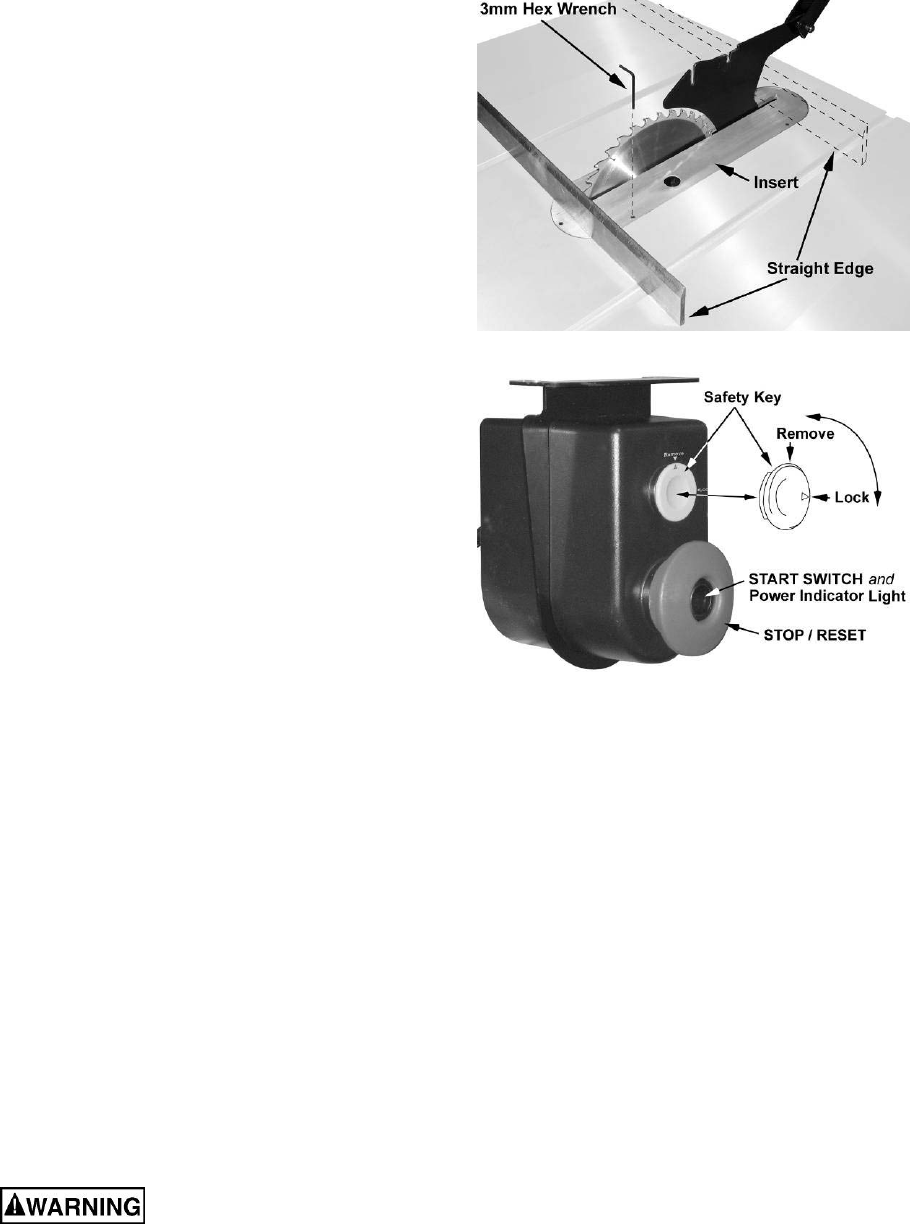
Insert Adjustment
Adjust the setscrews in the insert with a 3mm
hex wrench (Figure 20) to ensure that the insert
is stable and flush with the table top.
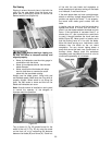
Arbor and Arbor Bearing Removal
The saw arbor is press fitted in the saw raising
arm housing. If the arbor needs to be removed
for bearing replacement, it should be done by a
qualified service technician. Call your customer
service representative at the phone number on
the front cover.
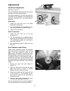
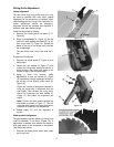
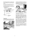
Operating Controls
Start/Stop
Power Indicator Light – The start switch has a
power indicator lamp which is on whenever
there is power connected to the saw, not just
when the saw is running. Do not assume that no
light means there is no power to the machine. If
the bulb is bad, there will be no indication.
Always check before use.
Do not rely that no light
means no power to the machine. Always
check for power first. Failure to comply may
cause serious injury!
Referring to Figure 21:
Start – Press the green start switch.
Figure 20
Figure 21
Stop – Press the red switch to stop.
Reset – In the event that the saw stops without
pressing the stop button, as the result of a
tripped fuse or circuit breaker, etc.:
1. Press red button to reset.
2. Press the green button to restart the
machine.
Safety Key
The start/stop switch is equipped with a
magnetic safety key. When in place on the
switch as shown in Figure 21, the magnetic
safety key trips a relay which will allow the
machine to start and stop when the respective
switches are pressed. Being magnetic, the lock
can be removed to make the machine inoperable
and can be hidden for safe storage by attaching
it underneath the rail or another magnetic
surface.
When using the saw, place the key on the switch
cover lining up the arrow on the key with the
REMOVE arrow on the cover. Then rotate the
key so the arrow lines up with the LOCK arrow.
This will prevent the safety key from coming
loose from vibration when the machine is in use.